
Magnetic triggering automatic fishing machine

A fishing device and automatic technology, applied in fishing accessories, fishing, applications, etc., can solve the problems of increased vigilance, small trigger force of trigger switch, and difficulty in sensitivity of trigger switch, so as to improve comfort and efficiency , to avoid the effect of misoperation

Pending Publication Date: 2017-10-10
德阳市夏季风渔具有限公司
View PDF7 Cites 0 Cited by
  • Summary
  • Abstract
  • Description
  • Claims
  • Application Information

AI Technical Summary

Problems solved by technology

However, it is a difficult problem to reasonably set the sensitivity of the trigger switch of this automatic fisher made of the principle of leverage
If the trigger force of the trigger switch is set too high, the fish will not be able to trigger the trigger switch, which will easily startle the fish and cause the fish to become more vigilant when eating bait again
If the trigger force of the trigger switch is set too small, it is easy to trigger the trigger switch by mistake before eating the bait, which cannot achieve the purpose of automatic fishing

Method used


Image

  • Magnetic triggering automatic fishing machine
  • Magnetic triggering automatic fishing machine

Examples


Embodiment 1

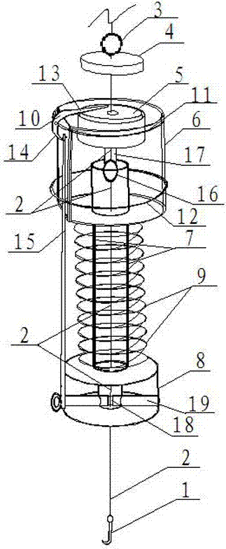
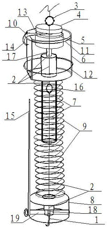
[0020] See figure 1 , figure 2 As shown: the present invention is a magnetically triggered automatic fishing device, which includes a fishing hook 1 and a fishing line 2 connected to the tail of the fishing hook 1. The fishing device also includes a trigger mechanism and an expansion mechanism.

[0021] The trigger mechanism is mainly composed of a buoyancy ball 3, an upper magnet 4, a lower magnet 5, a trigger lever 10, an upper spring ring 11 and a connecting rod 15. The buoyancy ball 3 provides the upper magnet 4 with buoyancy in the water; wherein, The upward buoyancy provided by the buoyancy ball 3 is equal to the gravity of the upper magnet 4, or the buoyancy of the buoyancy ball 3 is slightly greater than the gravity of the upper magnet 4, ensuring that the upper magnet 4 can float in the water after the expansion mechanism of the automatic fishing gear dives into the water. It maintains the state that it will not attract each other with the lower magnet 5, and also ensur...

Embodiment 2

[0030] The other structure of this embodiment 2 is the same as that of embodiment 1, but the difference is that the bottom end of the lower cylinder has a downwardly extending annular edge, which is used for ejecting from the lower cylinder along the fishing line direction on the hook side. When the second limiting hole of the cylinder body resists and is restricted to the hook tail of the fish hook, it buckles the fish mouth. Preferably, the ring edge opens outwardly in a flared shape.


PUM


Abstract

Provided is a magnetic triggering automatic fishing machine. The magnetic triggering automatic fishing machine includes a fish hook and a fish wire which is connected to the tail of the fish hook, and further includes a triggering mechanism and an expansion mechanism, the triggering mechanism includes a buoyant ball, an upper magnet, a lower magnet, a triggering lever, an upper spring ring and a connection rod, and the buoyant ball provides buoyancy force for the upper magnet; the expansion mechanism includes an upper cylinder, a guide cylinder and a lower cylinder, wherein the fish wire is sleeved with the upper cylinder, the guide cylinder is sleeved with a compression spring, the lower magnet is fixed to the top of the upper cylinder, a first limit hole and a second limit hole are correspondingly formed in the upper cylinder and the lower cylinder respectively, the upper cylinder and the lower cylinder are locked by the triggering lever, the upper spring ring and the connection rod which are made of a non-magnetic material, and the upper cylinder, the guide cylinder and a lower cylinder are assembled in sequence; in the direction of the fish hook, the buoyant ball, the upper magnet and a limit component are sequentially fixed to the fish wire, the portion, between the upper magnet and the limit component, of the fish wire is sleeved with the lower magnet and the upper cylinder, the lower magnet and the upper cylinder are integrally limited through the first limit hole, and the portion, between the upper magnet and the limit component, of the fish wire is sleeved with the lower magnet and the upper cylinder.

Description

Technical field [0001] The invention relates to a fishing gear, in particular to a magnetic trigger automatic fishing device. Background technique [0002] Traditional fishing gear often requires the angler to observe the state of the float for a long time and attentively, in order to grasp the timing of the lever. [0003] In order for anglers to be able to fish in a relatively comfortable state, from the long-term and attentive observation of the state of the fishing float, so as to grasp the timing of the lever to get rid of the current situation, automatic fishing equipment came into being. At present, most of the automatic fishing devices use the lever principle to make the trigger switch of the automatic fishing device. The trigger switch of the automatic fishing device is applied with a trigger force through the fish eating bait to trigger the trigger switch action of the automatic fishing device, thereby driving the whole A series of interlocking actions of the automatic f...

Claims


Application Information

Patent Timeline
IPC IPC(8): A01K93/00A01K97/00
CPCA01K93/00A01K97/00
Inventor 向磊
Owner 德阳市夏季风渔具有限公司
Learn More