
Stirring device for oil blending system

A technology of stirring device and oil agent, which is applied to mixers with rotary stirring devices, circuit devices, and accessories of mixers, etc., can solve problems such as affecting the spinning quality, and achieve the goal of improving profit margins, reducing production costs, and improving work efficiency. Effect

Inactive Publication Date: 2017-10-10
JIANGSU XINLONG CHEM FIBER MACHINERY
View PDF2 Cites 0 Cited by
  • Summary
  • Abstract
  • Description
  • Claims
  • Application Information

AI Technical Summary

Problems solved by technology

This oil tank can not solve the problems existing in the prior art, and still affects the quality of spinning

Method used


Image

  • Stirring device for oil blending system

Examples


Embodiment 1

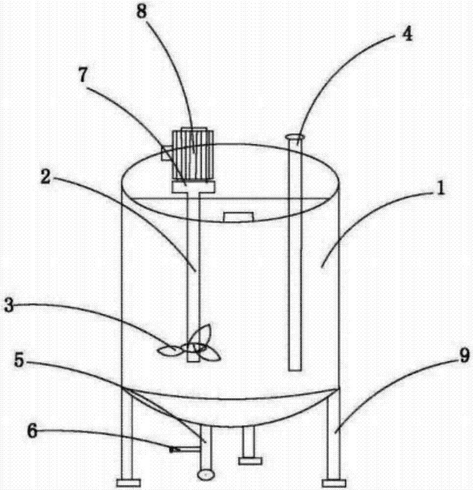
[0020] Embodiment 1: as figure 1 As shown, a stirring device for an oil preparation system includes a high-level oil tank 1, a stirring shaft 2 is inserted in the high-level oil tank 1, and a stirring impeller 3 is provided at the lower end of the stirring shaft 2. The high-level oil tank 1 is provided with an oil inlet pipe 4, the bottom of the high-level oil tank 1 is provided with a sewage pipe 5, and the side wall of the sewage pipe 5 is provided with an oil outlet 6. The top of the stirring shaft 2 is provided with a speed reducer 7, and the speed reducer 7 is rotated by a motor 8. The bottom of the high-level oil tank 1 is supported by legs 9 . A layer of thin-film solar cells is wrapped on the outside of the high-level oil tank.

[0021] The thin film solar cells are preferably CIGS, CIS thin film solar cells.

[0022] A storage battery can also be placed outside the stirring device and connected with the thin film solar cell. Used to store points generated by solar...


PUM


Abstract

The invention relates to a stirring device for an oil blending system, which is used for spinning production lines. The stirring device comprises a high-level oil groove, wherein a stirring shaft is inserted into the high-level oil groove; a lower end of the stirring shaft is provided with a stirring impeller; an oil inlet pipe is arranged in the high-level oil groove; the bottom of the high-level oil groove is provided with a discharge pipe; a side wall of the discharge pipe is provided with an oil outlet. The oil blending efficient stirring device is compact in structure; the product quality is enhanced, the service life of equipment is prolonged, and the working efficiency is increased.

Description

technical field [0001] The invention relates to a stirring device, in particular to a stirring device of an oil formulation system, which is used in a spinning production line. Background technique [0002] In the prior art, the oil dispensing link is very important in high-speed spinning production. Generally, the oil agent used in spinning production is prepared on a 24-hour basis. After the oil agent is prepared from the fourth floor, the oil agent is regularly released to the third floor according to the plan every day. There is a meeting period between the new oil and the old oil every day. In actual production, it is found that the problems in the spinning production during this period are prominent and summarized as follows: 1. A large number of paroxysmal broken ends during the concentrated period of spinning; 2. The cake is full of rolls, and there are many streaks and spots after dyeing. According to the process and oil analysis test, the oil will be delaminated du...

Claims


Application Information

Patent Timeline
Patent Type & Authority Applications(China)
IPC IPC(8): B01F7/18B01F15/00B01F15/02H02J7/35
CPCH02J7/35B01F27/90B01F35/2205B01F35/512B01F35/71805B01F35/7547Y02P90/50Y02P70/10
Inventor 金德贵聂德全戴振旺
Owner JIANGSU XINLONG CHEM FIBER MACHINERY
Learn More