Harvester brake fluid vacuum filling system and method

A technology for filling systems and brake fluids, applied in liquid distribution, conveying or transfer devices, special distribution devices, packaging, etc. Avoid malfunction of the main spool, easy to operate, and optimize the effect of the output pipeline

Inactive Publication Date: 2017-10-10
HENAN RICHUANG GENERAL MACHINERY MFR
View PDF9 Cites 1 Cited by
  • Summary
  • Abstract
  • Description
  • Claims
  • Application Information

AI Technical Summary

Problems solved by technology

Both of the above two methods need to exhaust the system. Loosen the bleed bolt on the brake cylinder respectively, step on the brake pedal until the liquid flows out from the bleed bolt without air bubbles, tighten the bleed bolt and brake The liquid level in the oil pot is replenished to the specified height, which is inconvenient to operate, and the exhaust operation increases the production process, and the discharge of brake fluid causes waste of production materials and pollutes the surrounding environment
[0003] The prior art closest to the present invention is the patent (Patent No.: 201110025026.8) titled "A Method and Equipment for Filling Motor Vehicle Brake Fluid". During the injection process, it is still necessary to loosen and tighten the opening bolts of the oil cylinder, which is inconvenient to operate

Method used


Image

  • Harvester brake fluid vacuum filling system and method
  • Harvester brake fluid vacuum filling system and method
  • Harvester brake fluid vacuum filling system and method

Examples


Embodiment 1

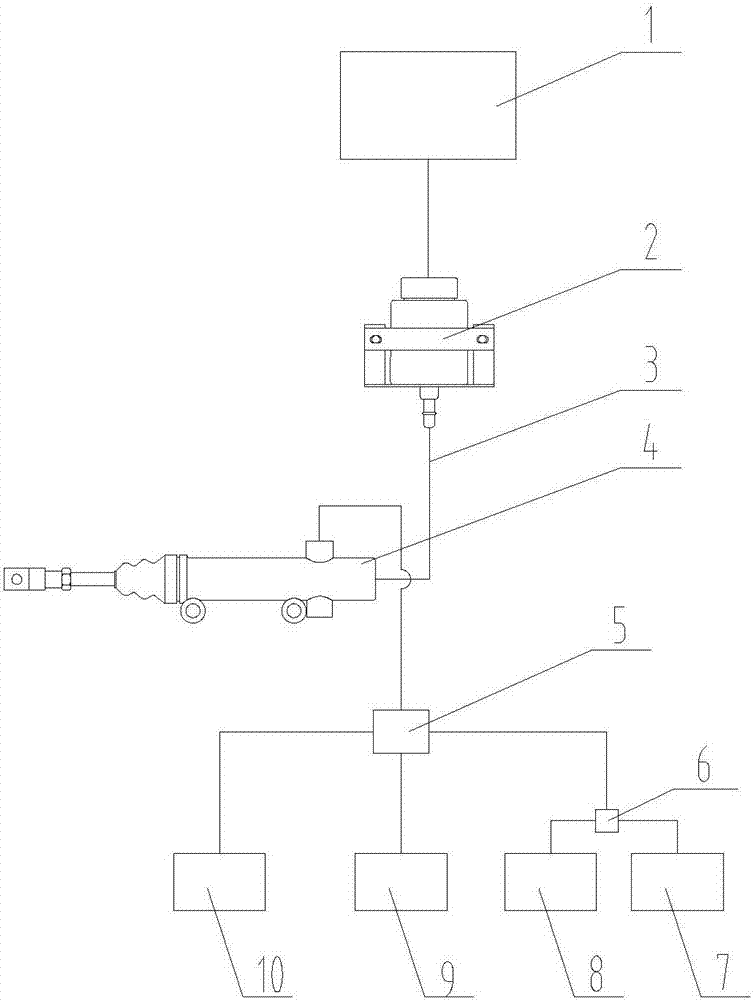
[0030] Such as figure 1 As shown, the harvester brake fluid vacuum filling system includes a brake oil pot 2 and a brake master cylinder 4, the oil outlet of the brake oil pot 2 is connected to the oil inlet of the brake master cylinder 4 through the brake pipeline 3, The oil outlet of the brake master cylinder 4 is respectively connected to the right rear wheel brake cylinder 7, the left rear wheel brake cylinder 8, the right front wheel brake cylinder 9, the left front wheel brake cylinder through the four-way joint body 5. Pump 10, the pipeline between the right rear wheel brake cylinder 7 and the left rear wheel brake cylinder 8 connects the tee joint body 6, which is the prior art. The harvester brake fluid vacuum filling system also includes a vacuum filling machine 1, and the filling gun head of the vacuum filling machine 1 is clamped and sealed with the filling port of the brake oil pot 2.

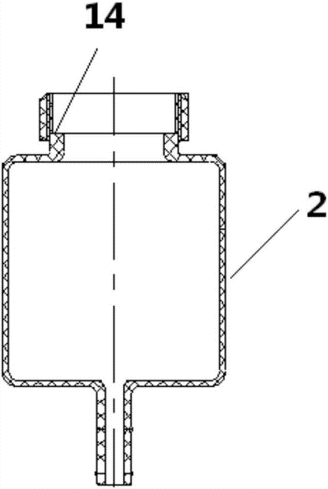
[0031] Such as figure 2 As shown, the filling port of the brake oil pot 2 i...

Embodiment 2

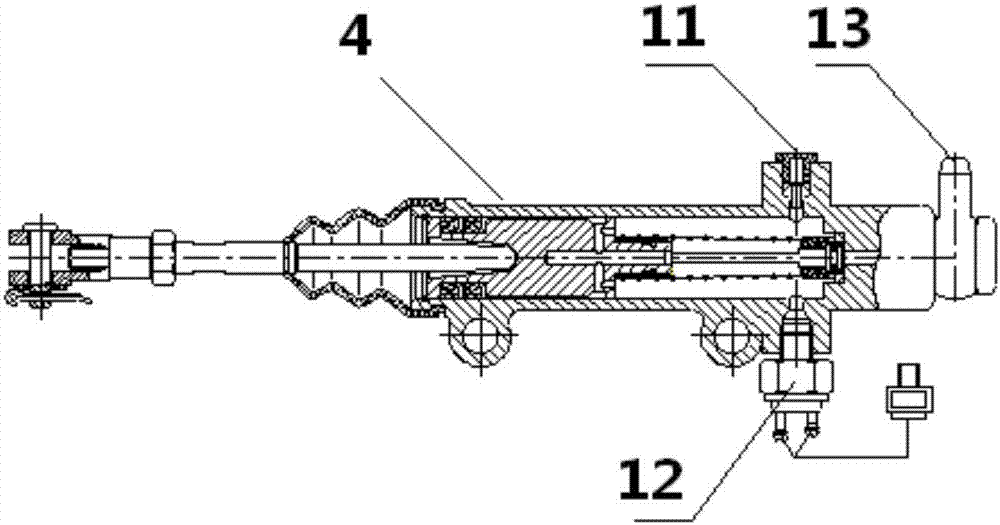
[0033] Such as image 3 As shown, the oil outlet 11 of the brake master cylinder 4 is located above the brake master cylinder, and the brake switch 12 is located below the brake master cylinder, corresponding to the position of the oil outlet 11 of the brake master cylinder. The oil inlet 13 of the pump is positioned at the top of the brake master cylinder tail. Other structures of the brake fluid vacuum filling system are the same as those in Embodiment 1.

[0034] When filling, include the following steps:

[0035] Step 1: Unscrew the cover of the brake oil pot, remove the inner cover and the filter screen of the oil pot, and place it in a nearby reliable place; clamp the filling gun head of the vacuum filler 1 to the fuel port of the brake oil pot 2, Vacuumize the gas in the brake oil pot 2, brake pipeline 3, brake master cylinder 4 and brake master cylinder output pipeline by filling the nozzle;

[0036] Step 2: Pressurize and inject brake fluid into the brake oil pot t...


PUM


Abstract

The invention relates to a harvester brake fluid vacuum filling system and method. The system comprises a brake oil can and a brake main pump; an oil outlet of the brake oil can is connected with an oil inlet of the brake main pump through a brake pipeline, and the system is characterized by further comprising a vacuum filling machine; a filling gun head of the vacuum filling machine is in clamped connection with an oil filling opening of the brake oil can in a seal manner; the filling gun head of the vacuum filling machine is clamped on the oil adding opening of the brake oil can, gas in the brake oil can, the brake pipeline, the brake main pump and an output pipeline of the brake main pump is subject to vacuum pumping through the filling gun head, brake liquid is injected in to the brake oil can in a pressured manner through the filling gun head, and oil in the brake oil can is sucked through the filling gun head until the height of the liquid level in the brake oil can reaches the set value. A hydraulic execution element does not need to loosened and fastened, the vacuum gun head is directly clamped on the filling opening of the brake oil can, vacuum pumping and filling can be finished, operation is more convenient, filling time is shortened, and the filling efficiency is effectively improved.

Description

technical field [0001] The invention relates to a harvester brake fluid vacuum filling system and method. Background technique [0002] At present, the brake fluid filling of the harvester is mostly filled manually. One way is to hold a small container and fill it with an appropriate amount of brake fluid into the brake oil pot; the other way is to use a small pumping device such as an electromagnetic pump to pump the brake fluid from the liquid storage tank into the brake oil pot to complete the filling process . Both of the above two methods need to exhaust the system. Loosen the bleed bolt on the brake cylinder respectively, step on the brake pedal until the liquid flows out from the bleed bolt without air bubbles, tighten the bleed bolt and brake The liquid level in the oil pot is replenished to the specified height, which is inconvenient to operate, and the exhaust operation increases the production process, and the discharge of the brake fluid causes waste of product...

Claims


Application Information

Patent Timeline
Patent Type & Authority Applications(China)
IPC IPC(8): B67D7/02B67D7/72B67D7/62
CPCB67D7/0277B67D7/62B67D7/725
Inventor 张振东魏本同黄玉华
Owner HENAN RICHUANG GENERAL MACHINERY MFR
Why Eureka
Try Eureka