Optical fiber isolator and optical fiber laser

An optical fiber isolator and energy transmission fiber technology, applied in the field of lasers, can solve the problems of inconvenient use, reduced performance of the optical fiber isolator, low sensitivity, etc., and achieve the effect of ensuring quality and reducing the ellipticity of the spot.

Active Publication Date: 2017-10-10
MAXPHOTONICS CORP
View PDF5 Cites 5 Cited by
  • Summary
  • Abstract
  • Description
  • Claims
  • Application Information

AI Technical Summary

Problems solved by technology

To heat the core of the isolator at constant temperature, the fiber optic isolator needs to be equipped with additional heating devices and temperature control devices, which will make the structure of the fiber optic isolator complex and inconvenient to use, and heating the isolator core at a constant temperature for a long time will cause high-temperature demagnetization, making the fiber optic isolator reduced performance of
To change the magnetic field strength of the magnetic rotation optical crystal, the optical fiber isolator needs to be equipped with an additional magnetic field strength control device, which will also lead to a complex structure of the optical fiber isolator and inconvenient use, and the magnetic field strength control device is mainly used to greatly adjust the optical rotation angle of the magnetic rotation optical crystal , the sensitivity of the adjustment is low to the slight change of the optical rotation angle caused by the change of the ambient temperature

Method used


Image

  • Optical fiber isolator and optical fiber laser
  • Optical fiber isolator and optical fiber laser
  • Optical fiber isolator and optical fiber laser

Examples


Embodiment Construction

[0026] In order to facilitate the understanding of the present invention, the present invention will be described more fully below with reference to the associated drawings. Preferred embodiments of the invention are shown in the accompanying drawings. However, the present invention can be embodied in many different forms and is not limited to the embodiments described herein. On the contrary, these embodiments are provided to make the understanding of the disclosure of the present invention more thorough and comprehensive.

[0027] Unless otherwise defined, all technical and scientific terms used herein have the same meaning as commonly understood by one of ordinary skill in the technical field of the invention. The terms used herein in the description of the present invention are for the purpose of describing specific embodiments only, and are not intended to limit the present invention. The terms "first", "second", "third" and the like in the claims, description and drawi...


PUM


Abstract

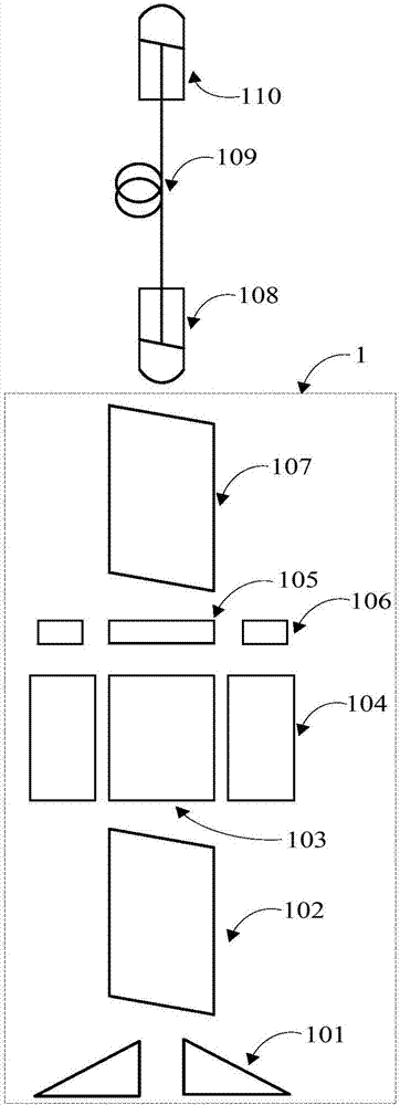
The embodiment of the invention discloses an optical fiber isolator and an optical fiber laser, and relates to the technical field of lasers. The optical fiber isolator comprises one or more light beam isolation structures, a coupling collimator, a transmitting energy fiber and an output collimator, wherein the transmitting energy fiber is connected with the coupling collimator and the output collimator; the light beam isolation structures comprise diaphragms, first beam splitters, magnetic optically-active crystals, magnets, half wave plates, fixing devices and second beam splitters, wherein the centers of light through holes of the diaphragms and the first beam splitters, the magnetic optically-active crystals, the half wave plates and center shafts of the second beam splitters are located in the same straight line; the optical-axis direction of the first beam splitters is mutually perpendicular to the optical-axis direction of the second beam splitters; the magnetic optically-active crystals are located in magnetic field areas of the magnets; the fixing devices drive the half wave plates to rotate to adjust the optical rotation angles of the half wave plates. The optical fiber isolator is simple in isolation degree structure and convenient to use.

Description

technical field [0001] The technical solutions disclosed in the embodiments of the present invention relate to the technical field of lasers, in particular to optical fiber isolators and optical fiber lasers. Background technique [0002] At present, the power of fiber lasers is increasing, and they are widely used in military, medical, industrial manufacturing and other fields. [0003] The isolator core, which consists of magneto-optical crystals and magnets, is sensitive to temperature. When the ambient temperature changes, the optical rotation angle of the magneto-optical crystal will also change, resulting in a reduction in the isolation of the optical fiber isolator for reverse light and weakening the transmission efficiency of forward light. [0004] In the process of researching the present invention, the inventor found that in the prior art, the reduction of the isolation of the optical fiber isolator is mainly avoided by maintaining the optical rotation angle of t...

Claims


Application Information

Patent Timeline
Patent Type & Authority Applications(China)
IPC IPC(8): G02F1/09
CPCG02F1/093
Inventor 曹际龙张浩泰邓杰蒋峰
Owner MAXPHOTONICS CORP
Why Eureka
Try Eureka