Laser wire stripping machine for transformer pins

A transformer and wire stripping machine technology, which is applied in the direction of transformer/coil connector, inductor/transformer/magnet manufacturing, line/collector components, etc., can solve the problems of high melting point of insulating layer and affect the stripping effect, and achieve improvement Efficiency, avoid inhalation hazards to health, avoid the effects of poor stripping quality

Inactive Publication Date: 2017-10-10
CHANGAN ANPINYUAN ELECTRONICS TECH CO LTD
View PDF0 Cites 4 Cited by
  • Summary
  • Abstract
  • Description
  • Claims
  • Application Information

AI Technical Summary

Problems solved by technology

[0002] In the existing transformer production process, in order to ensure the normal operation of transformer pin soldering, it is usually necessary to remove the insulation layer of the transformer pins before this, because the insulation layer on the pins has a high melting point, and ordinary electric soldering irons cannot meet the requirements. Therefore, the laser is used to strip the pin insulation layer. In the existing laser stripping process, it is necessary to manually replace the next set of transformers after stripping the pins of a group of transformers. At the same time, the existing The structure of the transformer tray is fixed, which cannot meet the needs of transformers of different sizes at the same time. During the laser stripping process, once the transformer shakes due to equipment vibration, the final stripping effect will be affected.

Method used


Image

  • Laser wire stripping machine for transformer pins
  • Laser wire stripping machine for transformer pins
  • Laser wire stripping machine for transformer pins

Examples


Embodiment Construction

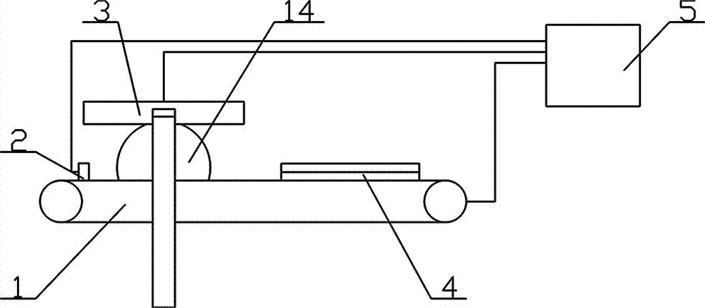
[0026] As shown in the figure, a laser wire stripping machine for transformer pins includes a transmission belt 1, a laser board 3 and a transformer tray 4, a laser board 3 is provided directly above one end of the transmission belt 1, and a laser generator is provided on the laser board 3. 13, the transformer tray 4 is placed on the conveyor belt 1.

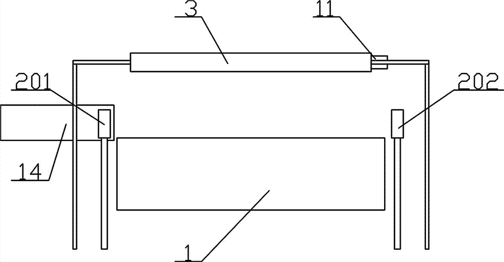
[0027] The preferred solution is as figure 2 Among them, the transmission belt 1 is provided with an infrared sensor 2 on both sides of one end of the laser plate 3, and the infrared sensor 2 includes an infrared emitting device 201 and an infrared receiving device 202, and the infrared emitting device 201 and the infrared receiving device 202 are respectively arranged on Both sides of the conveyor belt 1.

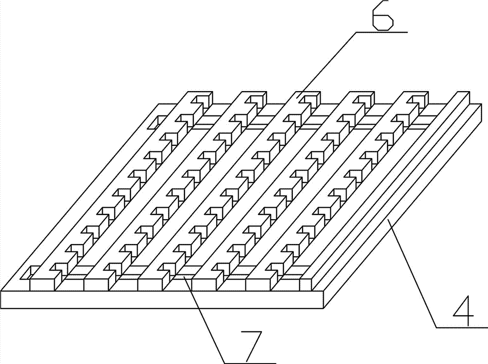
[0028] The preferred solution is as image 3 , Figure 5 Among them, the transformer tray 4 is provided with a plurality of transformer fixing bars 6, and each transformer fixing bar 6 is provided with a plurality of slo...


PUM


Abstract

A laser wire stripping machine for transformer pins, comprising a transmission belt, a laser plate and a transformer tray, a laser plate is provided directly above one end of the transmission belt, a laser generator is provided on the laser plate, and the transformer tray is placed on the transmission belt. The transmission belt is provided with infrared sensors on both sides of the end provided with the laser board, and the transformer tray is provided with a plurality of transformer fixing bars, and each transformer fixing bar is provided with a plurality of card slots. The bottom surface of the laser board is provided with the same number of second chutes as the number of transformer fixing bars, and a laser generator is provided in each second chute. The laser board is provided with a plurality of cylinders on the outside of one end of the second chute. It is connected with the laser generator through a push rod. By adopting the above-mentioned structure, the automatic stripping work of the transformer pins can be realized, which not only saves labor force, but also improves the efficiency of the stripping work and the quality of the final product.

Description

technical field [0001] The invention relates to the field of transformer production and processing, in particular to a laser wire stripping machine for transformer pins. Background technique [0002] In the existing transformer production process, in order to ensure the normal operation of transformer pin soldering, it is usually necessary to remove the insulation layer of the transformer pins before this, because the insulation layer on the pins has a high melting point, and ordinary electric soldering irons cannot meet the requirements. Therefore, the laser is used to strip the pin insulation layer. In the existing laser stripping process, it is necessary to manually replace the next set of transformers after stripping the pins of a group of transformers. At the same time, the existing The structure of the transformer tray is fixed, which cannot meet the needs of transformers of different sizes at the same time. During the laser stripping process, once the transformer shak...

Claims


Application Information

Patent Timeline
Patent Type & Authority Applications(China)
IPC IPC(8): H01F41/00H01R43/28
CPCH01F41/00H01R43/28H01R2201/22
Inventor 刘洪蛟向志勇
Owner CHANGAN ANPINYUAN ELECTRONICS TECH CO LTD
Why Eureka
Try Eureka