Current-position-based switched reluctance motor torque pulsation suppression method and system

A switched reluctance motor and torque ripple technology, applied in torque ripple control, motor generator control, electronically commutated motor control, etc., can solve difficult switch reluctance motor torque ripple, complex calculations, and inaccurate results And other issues

Active Publication Date: 2017-10-10
GUILIN UNIV OF ELECTRONIC TECH
View PDF4 Cites 13 Cited by
  • Summary
  • Abstract
  • Description
  • Claims
  • Application Information

AI Technical Summary

Problems solved by technology

The calculations of the existing methods are too complicated or the results are inaccurate, and it is difficult to effectively suppress the torque ripple of the switched reluctance motor

Method used


Image

  • Current-position-based switched reluctance motor torque pulsation suppression method and system
  • Current-position-based switched reluctance motor torque pulsation suppression method and system
  • Current-position-based switched reluctance motor torque pulsation suppression method and system

Examples


Embodiment Construction

[0058] Embodiment of Torque Ripple Suppression Method of Switched Reluctance Motor Based on Current-Position

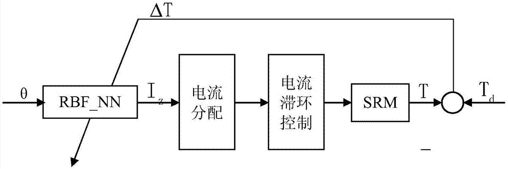
[0059] The current-position-based embodiment of the method for suppressing the torque ripple of the switched reluctance motor comprises the following steps:

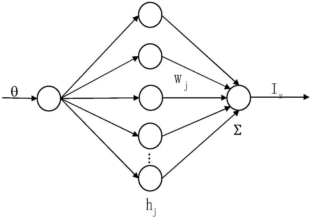
[0060] Step Ⅰ. Current-position neural network model

[0061] Ⅰ-1. The relationship between the sum of the squares of the phase currents and the torque

[0062] The mathematical model of SRM output torque is:

[0063]

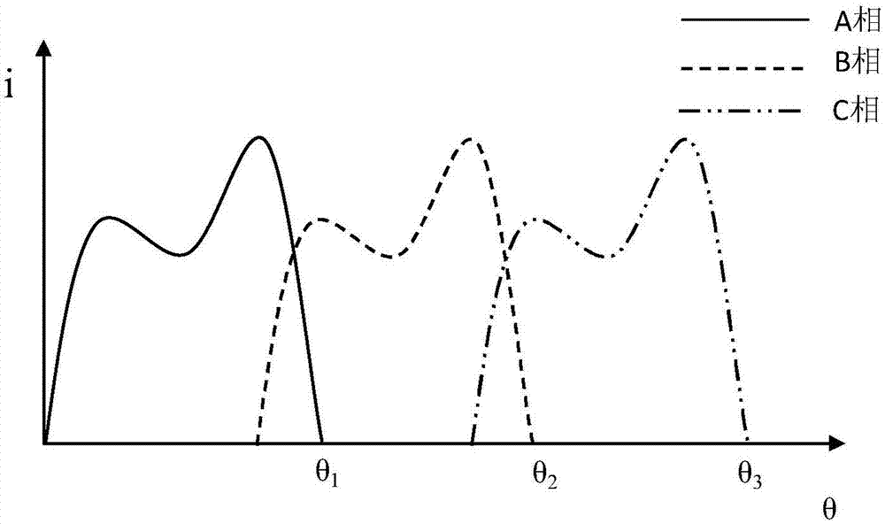
[0064] In formula (1), T kk is the value of the kkth phase torque; L kk is the value of the kkth phase inductance; i kk is the measured current value of the kkth phase; θ is the motor rotor position angle. kk=1,2,3, corresponding to phase A, B and C of SRM respectively.

[0065] Select the appropriate on-off angle, when the SRM magnetic circuit does not reach saturation, the phase inductance and the rotor position angle are approximately linear, The rate of change of inductance is appr...


PUM


Abstract

The invention discloses a current-position-based switched reluctance motor torque pulsation suppression method and system. According to the method, the sum of square of phase current is calculated directly by a rotor position angle based on a current-position neural network model to be used as the reference total current; a three-phase reference current is obtained through a distribution function; and the difference between the three-phase reference current and a three-phase actually-measured current is used as an input signal of a current lagging controller to control the operation of the switched reluctance motor. A system signal processor is connected with a current sensor, a torque sensor and a position sensor to receive a signal; and the current-position neural network model and a current distribution module performs calculation to obtain the input signal of the current lagging controller to control a power driver to drive the SRM. According to a periodical relation between the sum of square of phase current and the rotor position angle, the current-position neural network model is designed, so that the torque pulsation of the SRM is effectively lowered.

Description

technical field [0001] The invention relates to the technical field of control of switched reluctance motors for driving new energy vehicles, in particular to a method and system for suppressing torque ripple of switched reluctance motors based on current-position. Background technique [0002] SRM (Switched Reluctance Motor, SRM) has the characteristics of low cost, simple structure, good robustness and relatively high torque output, and is suitable for application in the field of new energy electric vehicles. However, the double salient pole structure of the switched reluctance motor, the highly nonlinear and strong coupling of the electromagnetic characteristics lead to large torque ripples during operation, especially at low speeds, and the noise caused by torque ripples is serious. Specific frequency The resonance problem is also more prominent. These disadvantages limit the application of switched reluctance motors in small electric vehicles. At present, there are tw...

Claims


Application Information

Patent Timeline
IPC IPC(8): H02P6/10H02P6/28H02P6/34H02P21/00H02P21/22H02P25/098
Inventor 党选举李珊党超陈恩普伍锡如张向文白雁力王凯利张潇司亚施亚洲
Owner GUILIN UNIV OF ELECTRONIC TECH
Why Eureka
Try Eureka