An engine fuel supply support plate casing structure and an engine comprising the structure

An engine and trigger technology, applied in the direction of engine lubrication, engine function, engine components, etc., can solve problems such as large aerodynamic loss, flow field disturbance, engine resonance, etc., to improve operation safety, reduce aerodynamic excitation force, Avoid the effects of higher order resonances

Active Publication Date: 2018-12-14
INST OF ENGINEERING THERMOPHYSICS - CHINESE ACAD OF SCI +1
View PDF8 Cites 0 Cited by
  • Summary
  • Abstract
  • Description
  • Claims
  • Application Information

AI Technical Summary

Problems solved by technology

However, this design brings the following problems: (1) the straight-leaf strut cannot adapt to the upstream airflow angle, resulting in a large aerodynamic loss; (2) the straight-blade strut cannot provide a suitable airflow angle for the downstream turbine stage, It is unfavorable to the aerodynamic performance of the downstream turbine, and increases the difficulty of additional low-pressure turbine design; (3) The straight-blade strut plate produces a very large disturbance to the flow field, which brings a large aerodynamic excitation force, which is easy to cause the downstream low-pressure turbine Low-cycle fatigue threatens the operation of the engine; (4) In order to ensure sufficient strength in the transition section, multiple support plates are generally designed, and evenly distributed support plates are likely to cause engine resonance problems, which is not conducive to the safe operation of the engine

Method used


Image

  • An engine fuel supply support plate casing structure and an engine comprising the structure
  • An engine fuel supply support plate casing structure and an engine comprising the structure
  • An engine fuel supply support plate casing structure and an engine comprising the structure

Examples


Embodiment Construction

[0023] In order to make the object, technical solution and advantages of the present invention clearer, the present invention will be further described in detail below with reference to the accompanying drawings and examples.

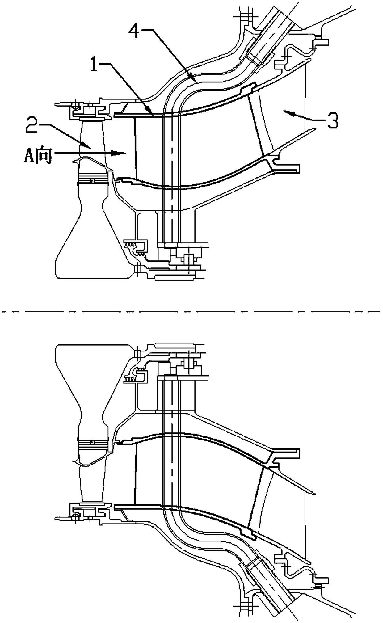
[0024] figure 1 It is a schematic diagram of assembly of the casing structure of the engine oil supply support plate of the present invention in the engine. 1 is the oil supply support plate casing, 2 is the high-pressure turbine rotor, 3 is the low-pressure turbine guide, and 4 is the lubricating oil pipeline. Among them, the high-pressure turbine rotor 1 is located upstream, the low-pressure turbine guide 3 is located downstream, and the oil supply support plate casing 1 is located in the transition section between the high-pressure turbine rotor 2 and the low-pressure turbine guide 3, and is welded to the low-pressure turbine The guides 3 are fixedly connected together. In order to ensure the welding effect, achieve a good supporting effect and pre...


PUM


Abstract

The invention discloses a novel engine oil supply support plate receiver structure and an engine comprising the structure. An oil supply support plate receiver is fixedly welded with a low-pressure turbine guider; multiple support plate blades in the oil supply support plate receiver are nonuniformly arranged in the peripheral direction to prevent resonance of an engine turbine part under high-speed operation condition; lubricating oil pipelines are arranged in at least one support plate blade, and are positioned on the lower side in the oil supply support plate receiver; each support plate blade is a three-dimensional torsional structure on space; at least two of multiple section blade shapes in different radial positions of the same support plate blade are different, so that each support plate blade can adapt to upstream incoming airflow angle and provide a proper flowing field to a downstream turbine, and pneumatic loss is obviously reduced; and the maximum thickness positions of different section blade shapes of each support plate blade are arranged in the same axial section, and are positioned on the same radial angle line, so that the support plate blades with the three-dimensional torsional structures can be smoothly arranged on the lubricating oil pipelines.

Description

technical field [0001] The invention relates to ground gas turbines, especially the turbine field of high-temperature components of aero-engines. More specifically, it adopts an oil supply support plate casing structure to improve the aerodynamic design structure between high and low-pressure turbine stages of aero-engines, reduce aerodynamic losses, and improve engine performance. Background technique [0002] In ground gas turbines and aero engines, in order to provide lubricating oil to the high pressure and low pressure rear bearings of the engine, a lubricating oil system needs to be arranged. To this end, a strut plate is formed in the transition between the high-pressure turbine and the low-pressure turbine. In order to meet the requirements of containing the lubricating oil pipe, the thickness of the support plate is often relatively large. In the existing engine design, for the convenience of design and processing, and limited by the detection method, these struts ...

Claims


Application Information

Patent Timeline
Patent Type & Authority Patents(China)
IPC IPC(8): F02C7/06
CPCF02C7/06F05D2260/96
Inventor 刘军杜强王沛胡嘉麟徐庆宗柳光高金海刘红蕊杨晓洁阮昌龙
Owner INST OF ENGINEERING THERMOPHYSICS - CHINESE ACAD OF SCI
Why Eureka
Try Eureka