Turbofan engine and spacecraft

A turbofan and engine technology, which is applied in the direction of machines/engines, gas turbine devices, mechanical equipment, etc., can solve the problems of complex structure of the compression system, disadvantages of length and weight, low fuel consumption, etc., and achieve simple structure and large duct ratio, the effect of reducing fuel consumption

Active Publication Date: 2019-03-08
AECC HUNAN AVIATION POWERPLANT RES INST
View PDF4 Cites 0 Cited by
  • Summary
  • Abstract
  • Description
  • Claims
  • Application Information

AI Technical Summary

Problems solved by technology

[0004] The present invention provides a turbofan engine and a spacecraft to solve the problem that the existing conventional turbofan engine achieves the purpose of high thrust and low fuel consumption, which leads to a complex structure of the high-pressure ratio compression system and disadvantages in terms of length and weight technical problem

Method used


Image

  • Turbofan engine and spacecraft
  • Turbofan engine and spacecraft
  • Turbofan engine and spacecraft

Examples


Embodiment Construction

[0023] The embodiments of the present invention will be described in detail below with reference to the accompanying drawings, but the present invention can be implemented in many different ways as defined and covered below.

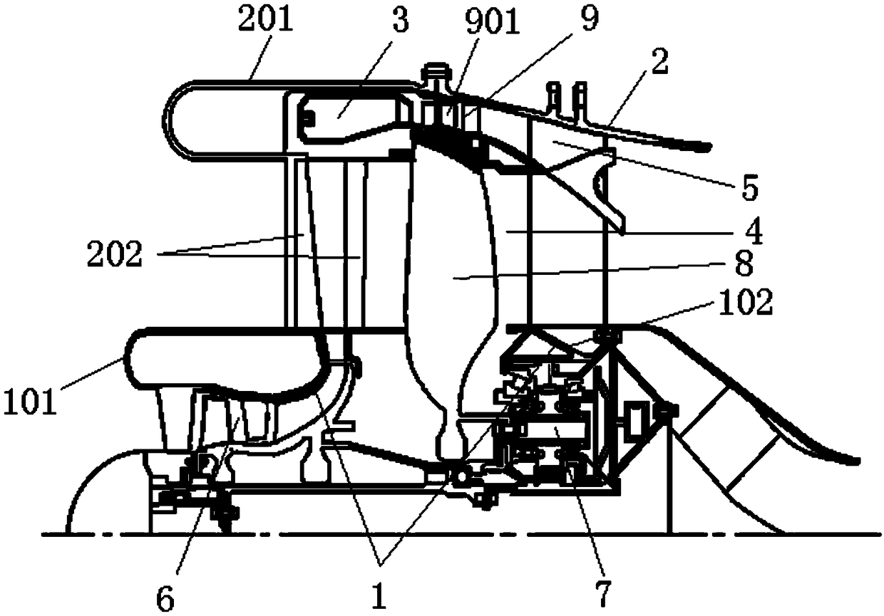
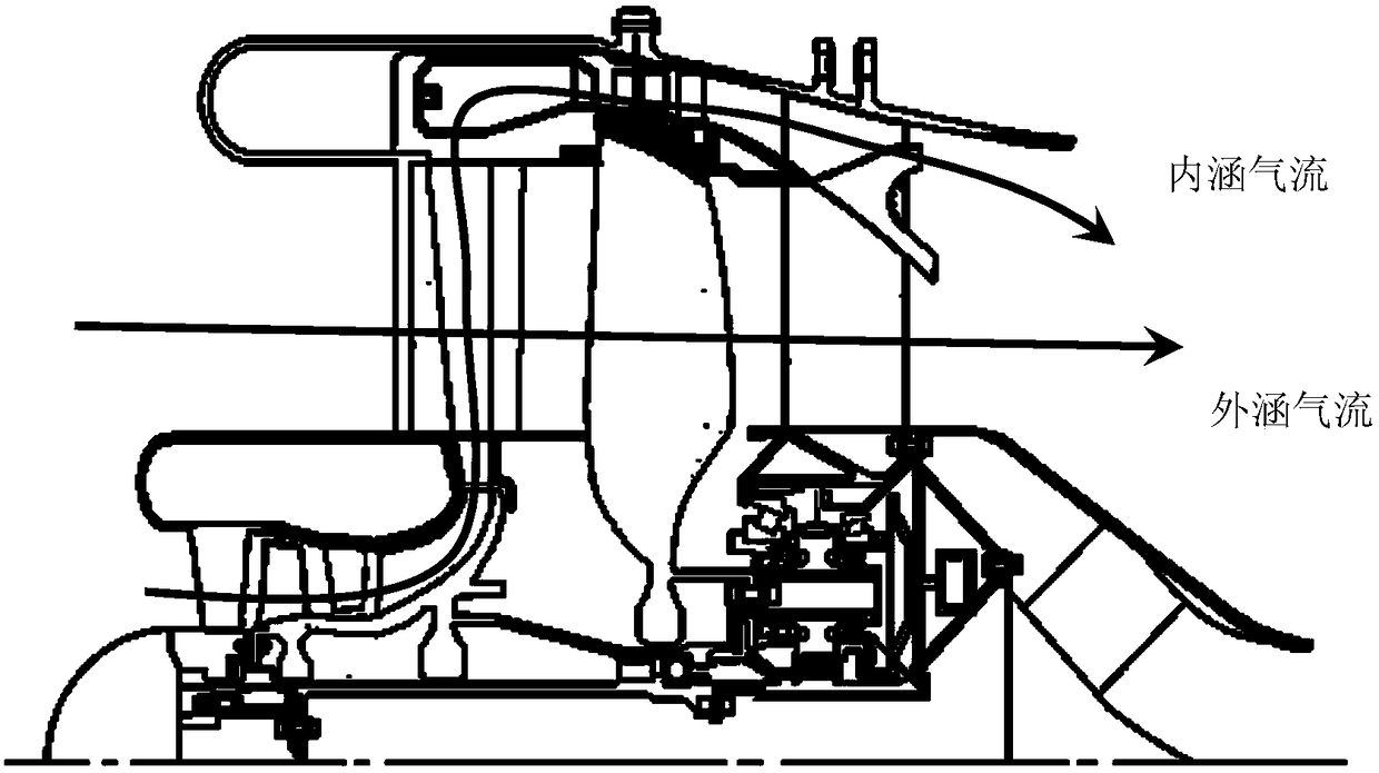
[0024] figure 1 is a schematic structural diagram of a turbo-turbofan engine according to a preferred embodiment of the present invention; figure 2 It is a working principle diagram of the bypass airflow of the turbo-turbofan engine according to the preferred embodiment of the present invention.

[0025] like figure 1 and figure 2 As shown, the turbo-turbofan engine of this embodiment includes an inner support structure 1 placed on the outer circumference of the main shaft and an outer support structure 2 placed on the outer circumference of the inner support structure 1, and the inner support structure 1 and the outer support structure 2 form a connotation The duct airflow channel 4, the combustion chamber 3 is placed in the outer support structu...


PUM


Abstract

The invention discloses a turbine turbofan engine and a spacecraft. The turbine turbofan engine comprises an inner supporting structure arranged at the periphery of a main shaft and an outer supporting structure arranged at the periphery of the inner supporting structure, wherein an outer bypass airflow channel is formed between the inner supporting structure and the outer supporting structure; a combustion chamber is arranged in the outer supporting structure positioned outside the outer bypass airflow channel; an inner bypass airflow channel enables air to flow from an air inlet of the inner supporting structure and communicates to the inside of the combustion chamber along a radially-penetrating outer bypass airflow channel. The whole structure of the turbine turbofan engine is simple, large bypass ratio can be realized at a temperature before a low turbine, the propulsive force of the engine is increased, and the oil consumption rate is reduced.

Description

technical field [0001] The present invention relates to the technical field of aero-engine structures, and in particular, to a turbo-turbofan engine. Furthermore, the present invention also relates to a spacecraft comprising the above turbo-turbofan engine. Background technique [0002] The fan, high-pressure compressor, combustion chamber, high-pressure turbine and low-pressure turbine of a conventional turbofan engine are on the same axis. The schematic diagram is as follows image 3 shown. The high-speed rotating fan compresses the air to a certain pressure, and the air is divided into two parts through the diverting device, one part of the air enters the outer duct, and the other part enters the inner duct. Compressed air entering the inner canal is compressed to a higher pressure by a high-pressure compressor rotating at a higher speed. After the high-pressure air enters the combustion chamber, it is quickly mixed with the fuel, and after being ignited, a high-tempera...

Claims


Application Information

Patent Timeline
Patent Type & Authority Patents(China)
IPC IPC(8): F02K3/062F02C3/14F02C3/04
CPCF02C3/04F02C3/14F02K3/062
Inventor 温泉杨志郭青林洪杰
Owner AECC HUNAN AVIATION POWERPLANT RES INST
Why Eureka
Try Eureka