
Reciprocating type pressurizer reversing device and application thereof

A technology of reversing device and supercharger, which is applied in the direction of fluid pressure actuating device, fluid pressure converter, servo motor assembly, etc. And other issues

Pending Publication Date: 2017-10-13
JINZHONG HAOPU HYDRAULIC EQUIP
View PDF0 Cites 10 Cited by
  • Summary
  • Abstract
  • Description
  • Claims
  • Application Information

AI Technical Summary

Problems solved by technology

The reciprocating supercharger is matched with a special reversing device, such as a hydraulic control reversing device disclosed in Chinese patent 2015206405567. The pilot port on one side of the pilot valve is connected to the pilot oil, and the pilot port on the other side releases pressure, so as to achieve continuous reversing of the supercharger. However, in the actual operation process, the following problems are prone to occur: 1. During the reversing process of the reversing valve, The piston chamber corresponding to the pilot port on the reversing side is disconnected from the oil supply pipeline, but the piston still keeps moving under the action of inertia. At this time, the above-mentioned piston chamber is in a negative pressure state, and the pilot oil in the hydraulic control check valve is instantly Pulling out causes the hydraulic control check valve to close early, the spool of the reversing valve is stuck in the neutral position, and the reversing fails; There is a lot of pilot oil, so when it changes direction, it is easy to cause pressure loss in the piston chamber of the supercharger, so that there will be pressure fluctuations at the output end, which will affect the supercharging effect

Method used


Image

  • Reciprocating type pressurizer reversing device and application thereof
  • Reciprocating type pressurizer reversing device and application thereof
  • Reciprocating type pressurizer reversing device and application thereof

Examples


Embodiment 1

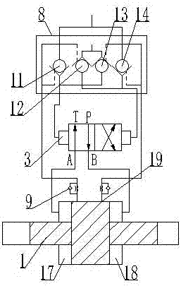
[0017] Such as figure 1 As shown, a reciprocating supercharger includes a first booster cylinder 1 , a first hydraulic control reversing valve 3 , and a hydraulic control check valve group 8 . The hydraulic control check valve group 8 includes a first hydraulic control check valve 11 , a second hydraulic control check valve 12 , a third hydraulic control check valve 13 and a fourth hydraulic control check valve 14 . The first pressurized cylinder includes a left piston chamber 17 and a right piston chamber 18, and the left and right piston chambers are equipped with an automatic control port 19. The first hydraulic control reversing valve 3 is a two-position four-way hydraulic control reversing valve, A and B ports are respectively connected to the end faces of the left and right piston chambers of the first booster cylinder 1, and the left pilot port is connected to the first hydraulic control check valve 11 and The third hydraulic control check valve 13, the right pilot por...

Embodiment 2

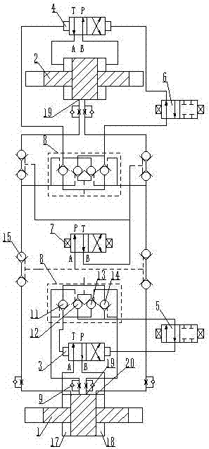
[0020] Such as figure 2 As shown, a single multi-control freely switchable reciprocating supercharger includes a first booster cylinder 1, a second booster cylinder 2, a first hydraulically controlled reversing valve 3, and a second hydraulically controlled reversing valve 4, each group The pressurized cylinder and the hydraulic control reversing valve match the hydraulic control check valve group 8, the hydraulic control check valve group 8 includes the first hydraulic control check valve 11, the second hydraulic control check valve 12, the third hydraulic control check valve Valve 13, the fourth hydraulic control check valve 14, the pressurized cylinder includes a left piston chamber 17 and a right piston chamber 18, the left and right piston chambers of the first pressurized cylinder are opened with an automatic control port 19 and an external control port 20, and the external control port is located at the automatic control port On the outside, the left and right piston c...

Embodiment 3

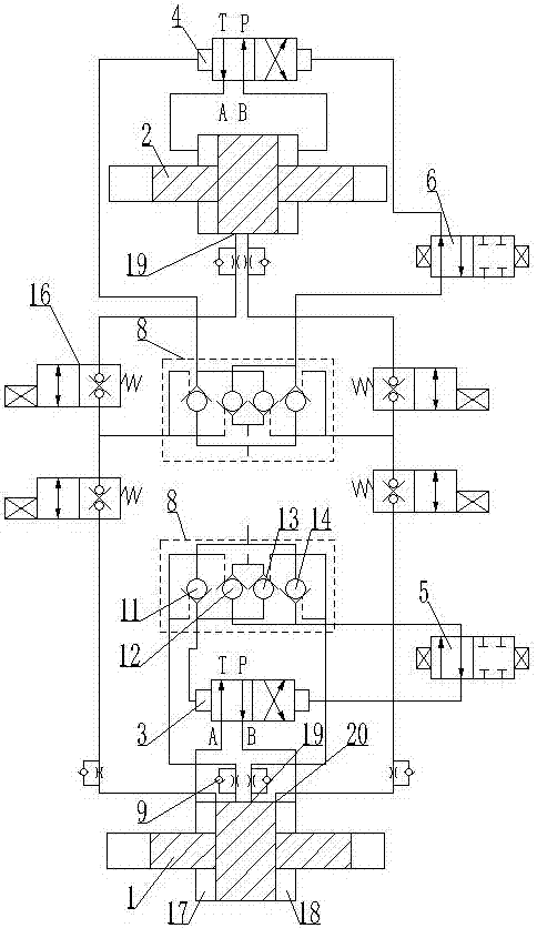
[0025] Such as image 3 As shown, in this embodiment, the two-way locking valve group and the first electromagnetic reversing valve in the second embodiment are replaced by electromagnetic ball valves, and the hydraulic control one-way valve group corresponding to the second booster cylinder can also be switched through the on-off of the electromagnetic ball valve. pilot control source. The action principle of this embodiment is the same as that of Embodiment 2 during pressurization operation.


PUM


Abstract

The invention discloses a reciprocating type pressurizer reversing device. The reciprocating type pressurizer reversing device comprises hydraulic control reversing valves and further comprises a hydraulic control one-way valve set; pilot ports in the two sides of the hydraulic control reversing valves communicate with an oil supply pipeline through the hydraulic control one-way valve set; pilot ports of hydraulic control one-way valves in the hydraulic control one-way valve set are connected to control ports of piston cavities of pressurization cylinders; and the control ports of the pressurization cylinders are each provided with a one-way throttling valve. According to the reciprocating type pressurizer reversing device, hydraulic cylinders indirectly control reversing of the hydraulic control reversing valves through the hydraulic control one-way valve set, due to the fact that the amount of oil liquid required by the pilot ports of the hydraulic control one-way valves is small, the pressure loss in the piston cavities of a pressurizer is extremely small, and normal pressure output of the piston cavities of the pressurizer cannot be affected; and the control ports of the piston cavities are provided with the one-way throttling valves, on the premise that the opening speed of the hydraulic control one-way valves is not affected, the pilot ports of the hydraulic control one-way valves are enabled to return oil normally and smoothly so that the phenomenon that the hydraulic control one-way valves are closed prematurely due to the fact that the piston cavities are in a negative pressure state can be effectively avoided, and therefore smooth reversing of the hydraulic control reversing valves can be realized.

Description

technical field [0001] The invention relates to a hydraulic reversing device, in particular to a reciprocating supercharger reversing device and its application. Background technique [0002] Hydraulic boosters are now widely used in various fields of industrial production. Among them, the reciprocating booster has a high usage rate because it does not require electronic control. The reciprocating supercharger is matched with a special reversing device, such as a hydraulic control reversing device disclosed in Chinese patent 2015206405567. The pilot port on one side of the pilot valve is connected to the pilot oil, and the pilot port on the other side releases pressure, so as to achieve continuous reversing of the supercharger. However, in the actual operation process, the following problems are prone to occur: 1. During the reversing process of the reversing valve, The piston chamber corresponding to the pilot port on the reversing side is disconnected from the oil supply ...

Claims


Application Information

Patent Timeline
Patent Type & Authority Applications(China)
IPC IPC(8): F15B13/06F15B3/00
CPCF15B3/00F15B13/06F15B2013/002
Inventor 佘喜旺王铁锁昝际伟暂际姣杜宜信王戈岩
Owner JINZHONG HAOPU HYDRAULIC EQUIP
Learn More