Spanner used for rotating gear and motor rotor rotating method

A technology for turning gears and wrenches, which is applied in the direction of wrenches, manufacturing stator/rotor bodies, and manufacturing tools. Inexpensive effect

Active Publication Date: 2017-10-17
CSR ZHUZHOU ELECTRIC CO LTD
View PDF9 Cites 1 Cited by
  • Summary
  • Abstract
  • Description
  • Claims
  • Application Information

AI Technical Summary

Problems solved by technology

All the above prior art can not be used to drive the motor rotor and increase the rotational speed and the number of turns of the motor rotor

Method used


Image

  • Spanner used for rotating gear and motor rotor rotating method
  • Spanner used for rotating gear and motor rotor rotating method
  • Spanner used for rotating gear and motor rotor rotating method

Examples


Embodiment Construction

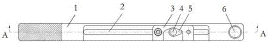
[0032] Through observation, it is found that the gear shaft press-fitted on the extension side of the motor shaft generally has a middle through hole (center hole), which is required for the manufacturing and assembly process. The center line of the gear shaft is the center line of the rotor rotation, the teeth on the outer edge of the gear shaft can play a meshing role, and the center distance is designed to be adjustable.

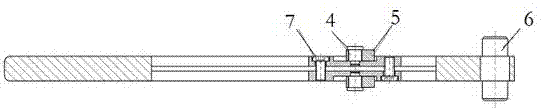
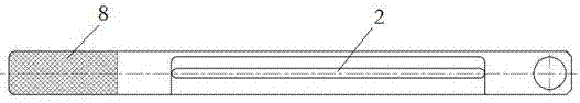
[0033] Please refer to Figure 1 to Figure 9 , A wrench 11 for rotating gears includes a main body 1, a movable block 3, a positioning pin 4, a movable tooth 5, a positioning pin 2 6, and a hexagon socket head cap screw 7. One end of the main body is set as a handle 8, and the two positioning pins are fixedly connected to the other end of the main body. The middle section of the main body is provided with a strip-shaped through hole 2 (movable slots can also be set on the front and back of the main body along the length direction of the main body, and the ...


PUM


Abstract

The invention discloses a spanner used for rotating a gear and a motor rotor rotating method. The spanner used for rotating the gear comprises a body part, a second locating pin, movable blocks and movable teeth; a handle is arranged at one end of the body part; the second locating pin is connected to the other end of the body part; the movable blocks are installed at the middle section of the body part; the movable teeth are installed on the movable blocks and can rotate within a preset angle. One end of the spanner is connected to a center hole through the locating pin, and the movable teeth are inserted into teeth at the periphery of a gear shaft; torque is applied to the other end of the spanner, is transmitted to the gear shaft through the spanner, and thus a rotor rotates. According to the spanner used for rotating the gear and the motor rotor rotating method, the labor intensity in the rotor rotating process is reduced, the rotation speed and the number of turns of the rotor are increased, the labor and time are saved, the rotation speed per time is high, the rotation time is long, the structure is simple, the manufacturing cost is low, and the thus the motor rotor rotating method is suitable for being developed in batch work.

Description

technical field [0001] The invention belongs to the technical field of motor manufacturing, and is applicable to the rotor disc movement requirements of all geared motors, especially for motor products with large rotor mass and difficult manual work, such as stator-rotor assembly, quality inspection and inventory motors of HXD1C series locomotive traction motors routine maintenance. Background technique [0002] During the process of assembly and quality inspection of the motor, the rotor often needs to be rotated in order to confirm that the assembly is correct and free of stagnation, and to detect the rotor runout value. In addition, for motors with a long storage time, it is necessary to stir the grease in the bearing lubrication system by rotating the rotor, so that the grease is evenly distributed, which is conducive to ensuring the lubrication effect. However, for locomotive motors including HXD1C series, the weight of the whole machine is about 2.5 tons, and the weig...

Claims


Application Information

Patent Timeline
Patent Type & Authority Applications(China)
IPC IPC(8): B25B13/48H02K15/02
CPCH02K15/02B25B13/48
Inventor 项永史新雷李赛华杨下沙
Owner CSR ZHUZHOU ELECTRIC CO LTD
Why Eureka
Try Eureka