Hydraulic driven type anti-pitching T-shaped hydrofoil with controllable attack angle

A drive-type, pitch-reducing technology, applied in the direction of using hydrofoils to act on the surrounding water surface to reduce ship motion, etc., can solve the problems of difficult maintenance, poor integrity, harshness, etc., to ensure control accuracy, improve anti-rolling effect, and enhance stability. sexual effect

Active Publication Date: 2017-10-17
HARBIN ENG UNIV
View PDF5 Cites 8 Cited by
  • Summary
  • Abstract
  • Description
  • Claims
  • Application Information

AI Technical Summary

Problems solved by technology

[0007] However, in order to make the hydrofoil have a variable angle of attack α, and to detect its attitude by installing precise sensors in the hydrofoil, the designer needs to consider the following four issues: First, when sailing at high speed, the head of the hydrofoil The cavitation that occurs at the location will lead to the deterioration of the hydrodynamic characteristics of the hydrofoil; second, the high-precision sensor has strict requirements on the working environment, and the hydrofoil needs to meet extremely high standards of sealing, moisture-proof and vibration-proof; third, the structure of the hydrofoil requires Ensure the safety and stability of sensor power supply and transmission lines; Fourth, the structure of the hydrofoil is relatively complex, the integrity is poor, the cost of design and manufacture is high, and maintenance is difficult

Method used


Image

  • Hydraulic driven type anti-pitching T-shaped hydrofoil with controllable attack angle
  • Hydraulic driven type anti-pitching T-shaped hydrofoil with controllable attack angle
  • Hydraulic driven type anti-pitching T-shaped hydrofoil with controllable attack angle

Examples


Embodiment Construction

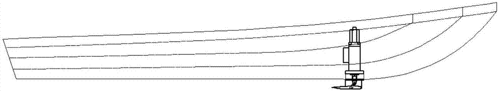
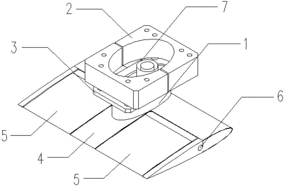
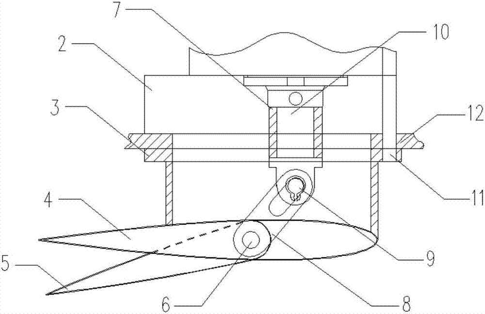
[0022] The overall technical solution is that the T-shaped hydrofoil is driven by a hydraulic cylinder, and the expansion and contraction of the piston rod of the hydraulic cylinder is converted into the synchronous deflection of the two flap tails through the mechanical transmission components. Because the size and connection mode of each mechanical transmission component are fixed, the expansion and contraction of the piston rod There is a quantitative relationship between the amount and the deflection angle α of the flap tail. A displacement sensor is installed on the piston rod to measure the expansion and contraction of the piston rod. By controlling the expansion and contraction of the piston rod, the semi-closed-loop control of the T-shaped hydrofoil angle of attack α can be realized. Thereby obtaining the expected pitching and heave righting moments. The present invention will be further described in detail below in conjunction with the accompanying drawings and specifi...


PUM


Abstract

The invention discloses a hydraulic driven type anti-pitching T-shaped hydrofoil with the controllable attack angle. The upper end of a column wing is installed on the lower portion of a keel of a ship bow, and the lower end of the column wing is perpendicularly welded to a horizontal fixed wing; a left tail flap and a right tail flap are symmetrically embedded in the horizontal fixed wing through a rotating shaft and can swing synchronously, and a swing gap is reserved between each tail flap and the horizontal fixed wing; the upper end of a connector of a hydraulic cylinder is connected with a piston rod of the hydraulic cylinder, and the lower end of the connector of the hydraulic cylinder is connected with a supporting arm in a hinged mode through a pin shaft; a sliding hole of the pin shaft is formed in the upper end of the supporting arm, and the lower end of the supporting arm is in rigid connection with the tail flaps; and a position magnetic ring and a measuring rod are installed in an airtight hydraulic cylinder body. According to the hydrofoil, the attack angle of the hydrofoil can be precisely controlled, the structure of the hydrofoil is optimized, stability, reliability and practicability are strengthened, and manufacturing and repairing difficulty is greatly reduced. The T-shaped hydrofoil can be combined with other anti-pitching accessory bodies in use, and the anti-pitching effect of a ship can be greatly promoted.

Description

technical field [0001] The invention belongs to the field of ship anti-rolling attachment devices, and in particular relates to a hydraulically driven anti-pitch T-shaped hydrofoil with a controllable angle of attack. Background technique [0002] When a ship is sailing at sea, due to the interference of the ocean environment such as wind and waves, the ship will pitch and heave. This negative effect is especially prominent for the widely used high-speed catamaran. In order to suppress this undesirable disturbance, anti-rolling attachments are usually installed on the hull, and T-shaped hydrofoils are a common anti-pitching attachment. Its anti-rolling principle is to make the fluid flow through the upper and lower airfoils differently to generate a pressure difference, thereby generating a longitudinal moment that resists wind and wave interference. The lift force of the T-shaped hydrofoil in the fluid can be expressed as: [0003] [0004] Among them: L is the hydrofo...

Claims


Application Information

Patent Timeline
Patent Type & Authority Applications(China)
IPC IPC(8): B63B39/06
CPCB63B39/06
Inventor 刘志林刘庭瑞朱齐丹孟浩蔡成涛吕晓龙曾薄文原新苏丽
Owner HARBIN ENG UNIV
Why Eureka
Try Eureka