A method for determining the start-up timing of deepwater drilling riser emergency release

An emergency release and deep-water drilling technology, which is applied in earthwork drilling, wellbore/well components, production fluids, etc., can solve the problems of not considering the transmission time lag and affecting the drilling timeliness, so as to ensure safe release and prolong the preparation time Effect

Active Publication Date: 2020-01-31
CHINA NAT OFFSHORE OIL CORP +1
View PDF3 Cites 0 Cited by
  • Summary
  • Abstract
  • Description
  • Claims
  • Application Information

AI Technical Summary

Problems solved by technology

These two methods need to be based on the same assumption that the offset of the drilling platform and the peak load response time of the riser wellhead system are consistent, but because the actual sea conditions, the distance between the drilling platform and the underwater wellhead may exceed thousands meters, the drilling platform has a large deviation under the action of surface waves and current loads, and it takes a certain amount of time to transfer the load to the subsea wellhead through a riser of thousands of meters. The deeper the water, the longer the transfer time. Therefore, the water There is a time lag between the lower wellhead load response and the drilling platform deflection
The conventional drilling riser release starting mechanism does not consider the lag of the transfer time, especially when the weakness of the whole system falls on the wellhead system, it often leads to early start of the riser release, and subsequent reconnection of the riser and the wellhead is required, seriously Affect the drilling time

Method used


Image

  • A method for determining the start-up timing of deepwater drilling riser emergency release
  • A method for determining the start-up timing of deepwater drilling riser emergency release
  • A method for determining the start-up timing of deepwater drilling riser emergency release

Examples


Embodiment Construction

[0029] The present invention will be described in detail below in conjunction with the accompanying drawings and embodiments.

[0030] The present invention provides a method for determining the starting timing of emergency release of a deepwater drilling riser, which specifically includes the following steps:

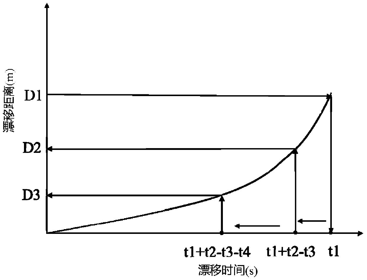
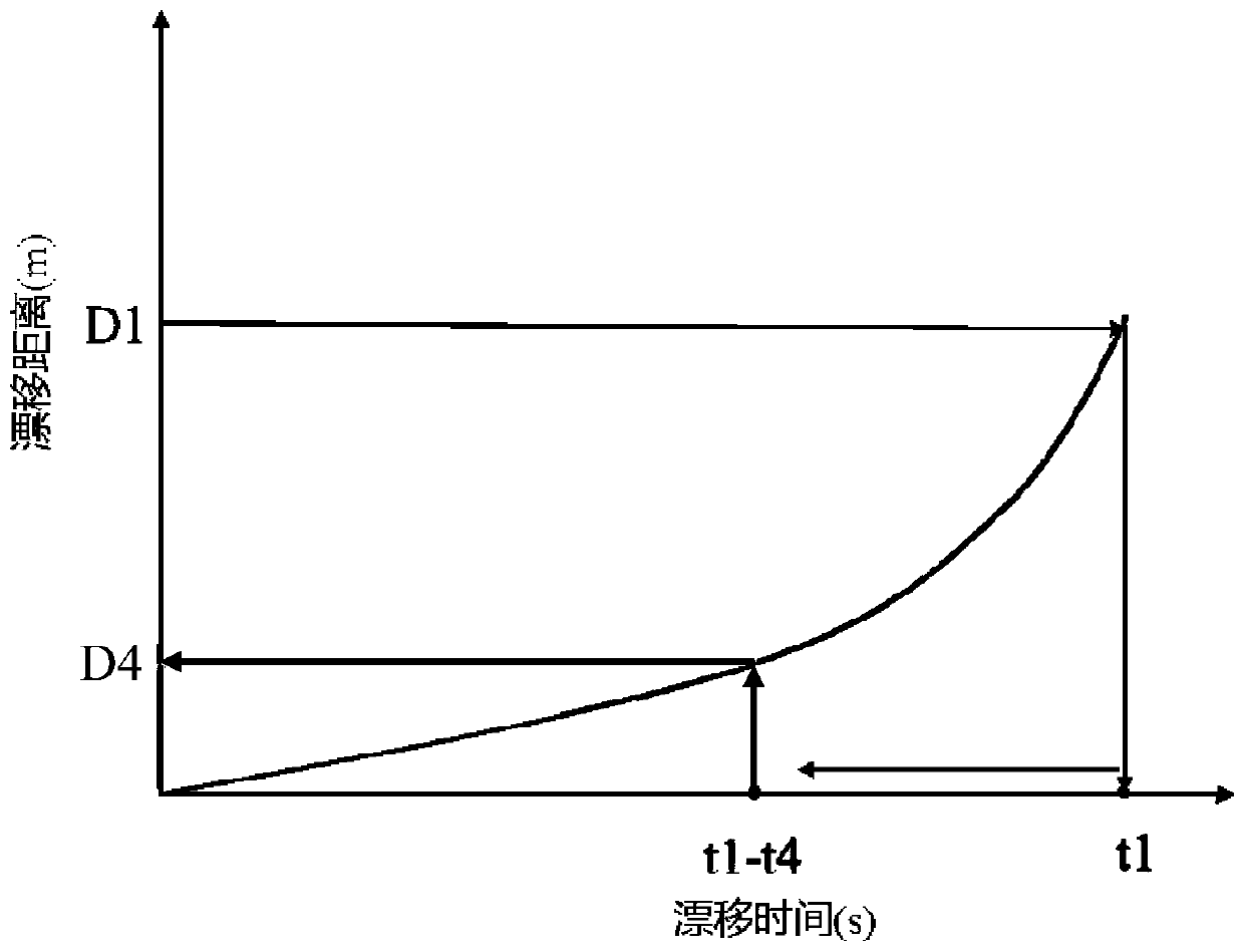
[0031] 1) Establish the motion analysis model of the target offshore drilling platform by using the classic floating body motion response method, and use the classic floating body motion response method to calculate the motion trajectory of the target offshore drilling platform when drifting occurs; plot the drift distance of the target offshore drilling platform with Drift curve of drift time variation. Such as figure 2 with image 3 As shown, the abscissa is the time of drifting, the ordinate is the distance of drifting, and the drifting curve represents the drifting track of the target offshore drilling platform.

[0032]2) Using the classic dynamic analysis met...


PUM


Abstract

The invention relates to a method for determining the starting opportunity for emergency releasing of a deepwater drilling riser. The method comprises the following steps of determining a weak component and a releasing position D1 of an offshore drilling platform; determining a time point t1 when the drilling riser of the offshore drilling platform is released; determining time t2 for transmitting a surface wave-current load to the weak component; determining execution time t3 for completing the emergency releasing action of the offshore drilling platform and calculating a time point t1+t2-t3 after the offshore drilling platform drifts and the corresponding drifting distance D2 of the offshore drilling platform; determining a time point t4 for preparing releasing starting of the offshore drilling platform, calculating a time point t1+t2-t3-t4 after drifting of the offshore drilling platform and the corresponding drifting distance D3 of the offshore drilling platform, and calculating a time point t1-t4 after drifting of the offshore drilling platform and the corresponding drifting distance D4 of the offshore drilling platform; and finally determining the starting opportunity for releasing of the drilling riser of the offshore drilling platform.

Description

technical field [0001] The invention belongs to the field of offshore oil and gas drilling and completion and oil and gas exploitation, and in particular relates to a method for determining the starting timing of emergency release of a deepwater drilling riser. Background technique [0002] Such as figure 1 As shown, offshore drilling establishes the connection between the deepwater drilling platform and the underwater wellhead through the drilling riser, and the drilling riser is responsible for isolating seawater and circulating drilling fluid. For offshore drilling, the drillship will move laterally with currents and waves. Since the position of the underwater wellhead is relatively static, when the displacement exceeds a certain value, the riser connected to it will bend and cause the wellhead to bend accordingly. For deepwater drilling, the most commonly used drilling platforms are automatically controlled through dynamic positioning. When encountering typhoons or str...

Claims


Application Information

Patent Timeline
Patent Type & Authority Patents(China)
IPC IPC(8): E21B43/013
CPCE21B43/013
Inventor 盛磊祥许亮斌周建良谢彬李朝玮
Owner CHINA NAT OFFSHORE OIL CORP
Why Eureka
Try Eureka