Car pilot-operated type fuel pump pressure regulator

A pilot-operated, fuel pump technology, applied in machine/engine, liquid fuel feeder, engine components, etc., can solve problems such as poor pressure characteristics, inability to match system pressure well, system pressure reduction, etc., to achieve pressure characteristics Good, low production cost, good pressure holding performance

Active Publication Date: 2017-10-17
CHONGQING WANLI LIANXING IND GROUP
View PDF5 Cites 0 Cited by
  • Summary
  • Abstract
  • Description
  • Claims
  • Application Information

AI Technical Summary

Problems solved by technology

The diaphragm of the valve diaphragm regulator is greatly affected by the working environment. When the temperature is lower than 30°C, the diaphragm will harden, resulting in excessive system pressure; when the temperature is above 60°C, the diaphragm will become soft and the system pressure will drop.
And because it is coated with nitrile rubber, it cannot be used for high methanol and ethanol fuels
And due to the use of the diaphragm mechanism, it cannot meet the needs of the ultra-high pressure fuel system
The diaphragm is also affected by the system pressure, which cannot match the system pressure well, and the pressure characteristics are poor

Method used


Image

  • Car pilot-operated type fuel pump pressure regulator

Examples


Embodiment 1

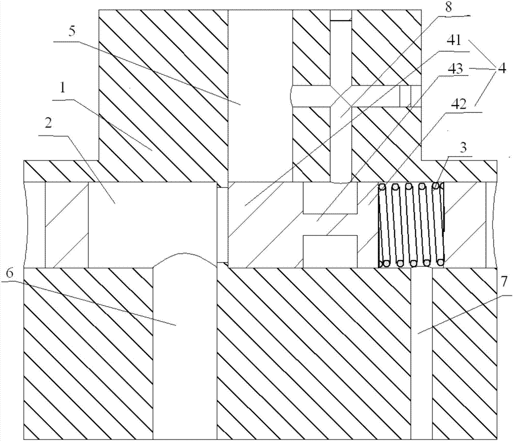
[0013] Example 1, such as figure 1 As shown, the automotive pilot fuel pump pressure regulator consists of valve body 1, fuel channel 2, pressure regulating spring 3, spool 4, oil inlet channel 5, first oil outlet channel 6, second oil outlet channel 7, bypass channel 8 composition.

[0014] The middle part of the valve body 1 is provided with a fuel channel 2 extending left and right, and the two ends of the fuel channel 2 are sealed. The valve body 1 below the fuel passage 2 is also provided with a first oil outlet passage 6 and a second oil outlet passage 7 whose axis extends up and down from left to right, and the upper ends of the first oil outlet passage 6 and the second oil outlet passage 7 are connected to The fuel oil channel 2 communicates, the oil inlet channel 5 is located between the first oil outlet channel 6 and the second oil outlet channel 7, the inner diameter of the second oil outlet channel 7 is smaller than the inner diameter of the first oil outlet chann...


PUM


Abstract

The invention discloses a car pilot-operated type fuel pump pressure valve. A fuel channel with the axis extending in the left-right direction is formed in the middle of a valve body, and the two ends of the fuel channel are sealed. The lower end of a fuel feeding channel communicates with the fuel channel, the upper ends of a first fuel discharging channel and a second fuel discharging channel communicate with the fuel channel, and the fuel feeding channel is located between the first fuel discharging channel and the second fuel discharging channel. A side channel is formed in the middle of the fuel feeding channel, and the lower end of the side channel communicates with the fuel channel and located between the fuel feeding channel and the second fuel discharging channel. A valve core is mounted in the fuel channel, the right end of the valve core is connected with a pressure adjusting spring, and the pressure adjusting spring tightly abuts against the right end of the fuel channel. The valve core comprises a left valve core body and a right valve core body, a gap is formed between the left valve core body and the right valve core body, and the left valve core body and the right valve core body are connected through a connecting part. The left valve core body is located below the fuel feeding channel, the connecting part is located below the side channel, and the right valve core body is located between the side channel and the second fuel discharging channel. Pressure maintaining is stable, and the pressure characteristic is good.

Description

technical field [0001] The invention relates to a pressure regulator of an automobile pilot type fuel pump, which belongs to automobile accessories. Background technique [0002] Traditional electric fuel pumps generally use diaphragm fuel pressure regulators. The pressure regulator of this kind of structure relies on the diaphragm and the spring to form the pressure system, the cost is high, and the process is complicated. One of the diaphragm has long been dependent on imports. The diaphragm of the valve diaphragm regulator is greatly affected by the working environment. When the temperature is lower than 30°C, the diaphragm will harden, resulting in excessive system pressure; when the temperature is above 60°C, the diaphragm will become soft and the system pressure will drop. And because it is coated with nitrile rubber, it cannot be used for high methanol and ethanol fuels. Moreover, due to the use of a diaphragm mechanism, it cannot meet the requirements of an ultra-...

Claims


Application Information

Patent Timeline
Patent Type & Authority Applications(China)
IPC IPC(8): F02M37/00
CPCF02M37/0023Y02T10/30
Inventor 徐猛张明健张曦李阳刘诗会
Owner CHONGQING WANLI LIANXING IND GROUP
Why Eureka
Try Eureka