Supercharge Your Innovation With Domain-Expert AI Agents!

Fluid heating device

一种加热装置、流体的技术,应用在流体加热器、欧姆电阻加热装置、水加热器等方向,能够解决电路功率因数降低、电压降低等问题,达到改善电路功率因数、提高设备效率的效果

Inactive Publication Date: 2017-10-17
TOKUDEN CO LTD
View PDF4 Cites 0 Cited by
  • Summary
  • Abstract
  • Description
  • Claims
  • Application Information

AI Technical Summary

Problems solved by technology

[0004] However, when an AC voltage is applied to both ends of the conductor tube, the voltage drops due to the inductance of the conductor tube, so there is a problem that the power factor of the circuit that applies the AC voltage to the conductor tube decreases.

Method used


Image

  • Fluid heating device
  • Fluid heating device
  • Fluid heating device

Examples


no. 1 approach

[0058] An embodiment of the fluid heating device of the present invention will be described below with reference to the drawings.

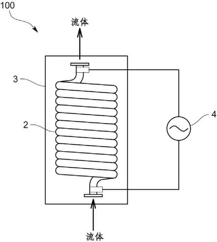
[0059] Such as figure 1 As shown, in the fluid heating device 100 of this embodiment, a three-phase AC power source 4 is connected to a hollow conductor tube 2. A fluid (for example, water, saturated steam, or superheated steam, etc.) flows inside the conductor tube 2 and passes through The conductor tube 2 is directly energized by applying a three-phase AC voltage, and uses the Joule heat generated by the internal resistance of the conductor tube 2 to heat the conductor tube 2 to heat the fluid flowing in the conductor tube 2.

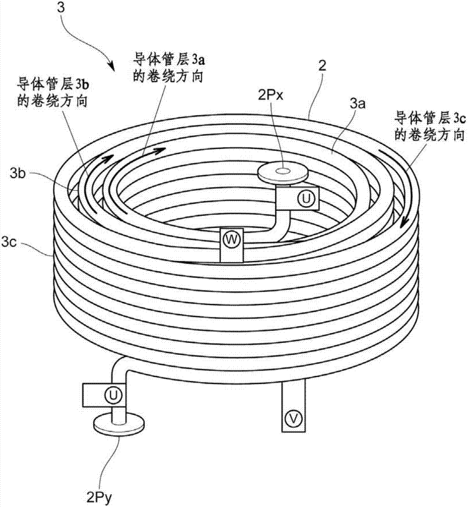
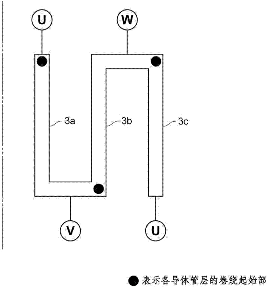
[0060] Specifically, the fluid heating device 100 includes a fluid heating part 3, which is formed by winding a single conductor tube 2 or a plurality of conductor tubes 2 electrically connected to each other into a spiral 3N (N is 1 or more) Integer) layer of conductor tube layer.

[0061] The fluid heating part 3 is such as ...

no. 2 approach

[0090] Next, the second embodiment of the present invention will be described.

[0091] The fluid heating device 100 of this embodiment has a fluid heating part 3 composed of one conductor tube 2 or a plurality of conductor tubes 2 electrically connected to each other.

[0092] The fluid heating part 3 is such as Figure 7 ~ Figure 10 As shown, various structures can be adopted.

[0093] Figure 7 The fluid heating section 3 shown is composed of two conductor tubes 2 electrically connected by an AC circuit including an AC power source 4. The impedance value of the entire fluid heating section 3 is equally divided into even-numbered parts (in this embodiment). The two ends of the split elements 3a and 3b are applied with an AC voltage from the AC power supply 4.

[0094] Each divided element 3a, 3b is a conductor tube layer formed by winding a conductor tube 2 having fluid inlets and outlets 2Px, 2Py at both ends through which the fluid to be heated flows in or out. In addition, the ...


PUM


Abstract

The invention provides a fluid heating device capable of improving the circuit power factor and increasing the efficiency of equipment. The fluid heating device is provided with 3N conductor pipe layers, wherein conductor pipes (2) are wound into a spiral shape to form each conductor pipe layer. The impedance values of the conductor pipe layers are substantially equal to each other and the conductor pipe layers are wound along the same direction to form a concentric circle shape.

Description

[0001] This application is a divisional application of the patent application No. 201310047091.X with the filing date of February 5, 2013 and the title of the invention "fluid heating device". Technical field [0002] The invention relates to a fluid heating device using AC power. Background technique [0003] As shown in Patent Document 1, there is known a fluid heating device that energizes and heats a hollow conductor tube and heats a fluid flowing inside the conductor tube to generate a heating fluid. In the fluid heating device, by applying an AC voltage from electrodes provided at both ends of the conductor tube, the AC current flows on the side wall of the conductor tube, and the conductor tube heats itself due to Joule heat generated by the internal resistance of the conductor tube. The self-heating of the conductor tube is used to heat the fluid flowing in the conductor tube. [0004] However, when an AC voltage is applied to both ends of the conductor tube, the voltage dr...

Claims


Application Information

Patent Timeline
Patent Type & Authority Applications(China)
IPC IPC(8): F24H1/16F22B1/28F22G1/16H05B3/40
CPCF22B1/28F22G1/165F24H1/162H05B3/40H05B3/0052H05B3/03H05B3/58
Inventor 外村徹藤本泰広
Owner TOKUDEN CO LTD
Features
  • R&D
  • Intellectual Property
  • Life Sciences
  • Materials
  • Tech Scout
  • Unparalleled Data Quality
  • Higher Quality Content
  • 60% Fewer Hallucinations
Learn More