Creep aging bidirectional tension-compression testing device

A creep aging and test device technology, applied to measuring devices, instruments, scientific instruments, etc., to achieve the effect of easy installation, simple structure and easy maintenance

Active Publication Date: 2017-10-17
CENT SOUTH UNIV
View PDF10 Cites 6 Cited by
  • Summary
  • Abstract
  • Description
  • Claims
  • Application Information

AI Technical Summary

Problems solved by technology

[0011] The purpose of the present invention is to provide a creep aging bidirectional tensile and compressive test device to solve the technical problem that the prior art structure cannot perform bidirectional compression on the specimen or perform a compression test while stretching

Method used


Image

  • Creep aging bidirectional tension-compression testing device
  • Creep aging bidirectional tension-compression testing device
  • Creep aging bidirectional tension-compression testing device

Examples


Embodiment 1

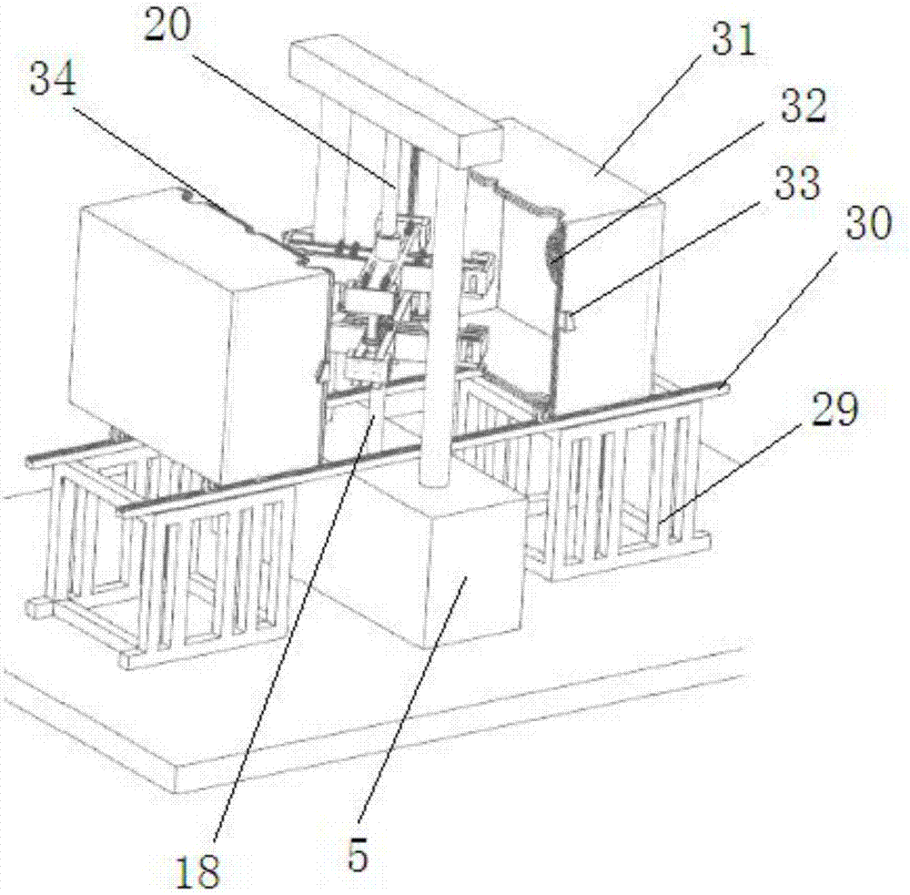
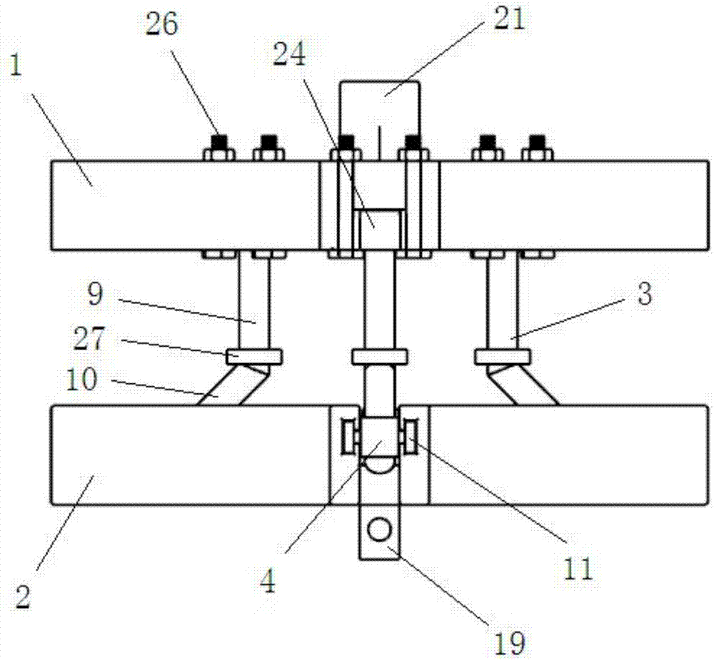
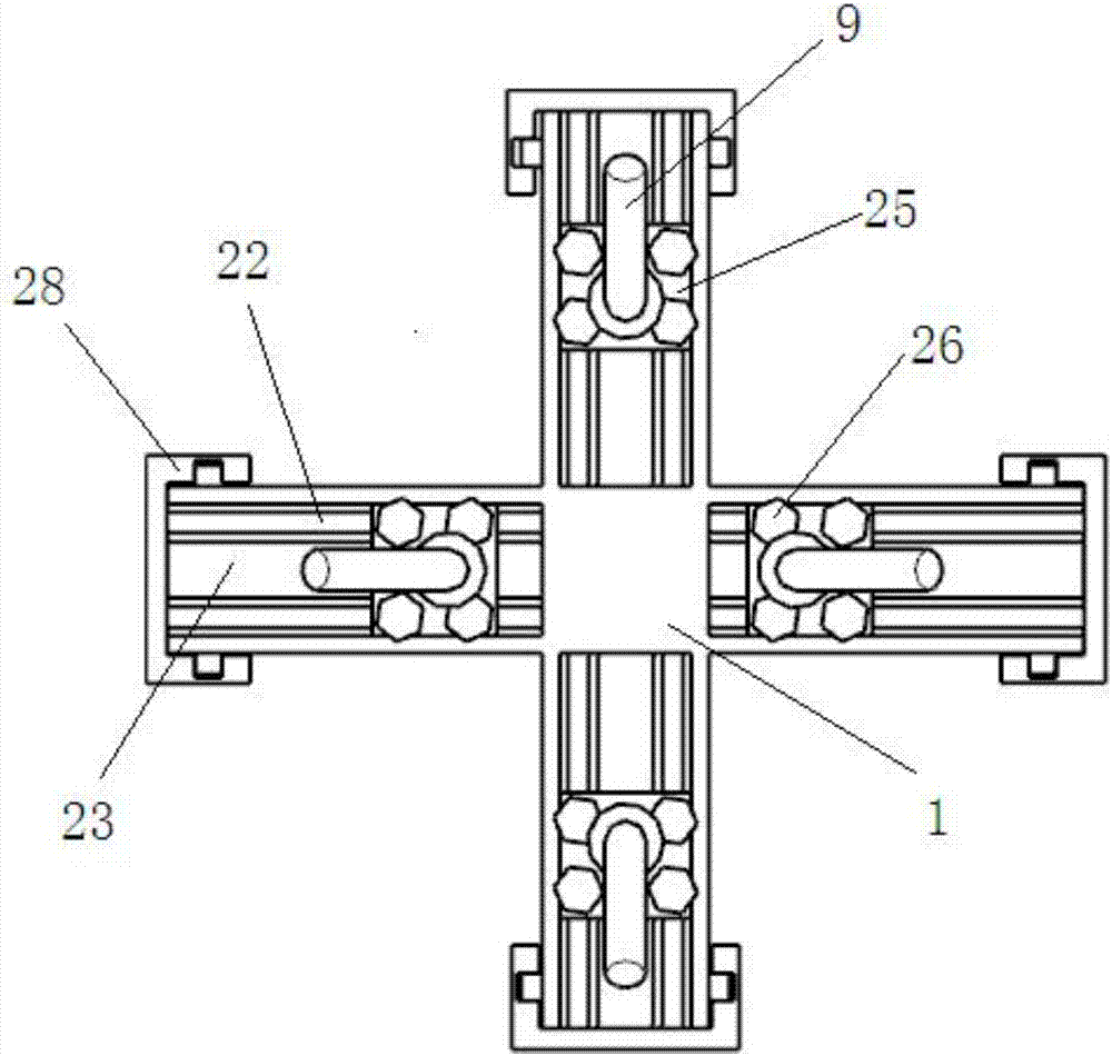
[0050] see Figure 1-Figure 6 , a creep aging bidirectional tension and compression test device, including an upper cross support 1, a lower cross support 2, four guide post assemblies 3 and four slider assemblies 4.

[0051] The upper end cross bracket and the lower end cross bracket are arranged on the same central axis from top to bottom, and the central part of the lower end cross bracket is provided with a lower connecting piece 19 connected with the lower connecting rod 18 of the stretching machine 5, the upper end The central portion of the cross bracket is provided with an upper connecting piece 21 connected with the upper connecting rod 20 of the stretching machine 5 and the upper connecting rod provides a vertical upward pulling force for the upper end cross bracket, and the lower connecting piece and the upper connection The components are rod structures and are sleeved and connected with the lower connecting rod and the upper connecting rod respectively.

[0052] ...

Embodiment 2

[0064] See details Figure 7 , the device of this embodiment is mainly used for bidirectional compression test. At this time, as long as the guide post assembly in embodiment 1 is rotated 180° along the axis of the straight guide post, so that the upper ends of the four inclined guide posts are all facing away from the The direction of the free end of the second groove is inclined, and the pulling force of the stretching machine drives the upper cross bracket to move upward, thereby driving the straight guide column and the inclined guide column to move upward, but because the slider can only move horizontally , and the inclined guide post is matched with the inclined hole of the slider, so the end of the inclined guide post pushes the slider to slide toward the free end side of the second groove, so that the slider pushes The free end of the cross-shaped specimen is compressed inwardly.

Embodiment 3

[0066] See details Figure 8 , the device of this embodiment is mainly used for doing a compression test while stretching, combining the structures of Embodiment 1 and Embodiment 2, and controlling the freedom of the upper ends of one set of two opposite inclined guide posts toward the second groove. The end side is inclined, and the upper ends of the other set of two opposite inclined guide posts are inclined toward the free end side away from the second groove.


PUM


Abstract

The invention provides a creep aging bidirectional tension-compression testing device which comprises an upper component, a lower component, a guide column component as well as a temperature box, wherein the upper component and the lower component are arranged according to a same central axis; the guide column component is arranged between the upper component and the lower component; the lower component and the upper component are respectively connected with a lower connecting rod and an upper connecting rod of a tension machine; the upper connecting rod is used for providing upright tension to the upper component; a second groove for holding a cross test piece is formed in the upper surface of the lower component; sliding grooves are respectively formed in end parts of four free ends of the second groove; sliding block components are arranged inside the sliding grooves; the guide column component comprises a straight guide column and an inclined guide column from top to bottom in a serial connection manner; upper and lower ends of the straight guide column are respectively fixed with the upper component and the upper end part of the inclined guide column; the lower part of the inclined guide column and the free ends of the cross test piece are both connected with the sliding block components; and the temperature box is used for providing different temperatures. By adopting the device, testing of bidirectional tension, bidirectional compression and tension and compression upon the cross test piece can be carried out at different temperatures.

Description

technical field [0001] The invention relates to the field of detection of creep aging properties of metal plates, in particular to a creep aging bidirectional tension-compression test device. Background technique [0002] With the rapid development of the modern aerospace industry, the requirements for aircraft performance are getting higher and higher, and many main load-bearing components such as aircraft joints, girders, partitions, wing frames, etc. are widely used in integral structural design. Creep age forming technology is a new technology developed for the preparation of large integral wall panels. [0003] At present, people still mainly use single tensile test or biaxial tensile test method to study the creep aging formability of aluminum alloy and other materials. ; ② Use two or more independent drive systems to complete bidirectional stretching. [0004] The first category mainly includes multiple times of unidirectional stretching to achieve bidirectional str...

Claims


Application Information

Patent Timeline
Patent Type & Authority Applications(China)
IPC IPC(8): G01N3/00G01N3/02
CPCG01N3/00G01N3/02G01N2203/0019G01N2203/0012G01N2203/0017G01N2203/0254G01N2203/0435G01N2203/0282G01N2203/0071G01N2203/0226Y02E60/10
Inventor 湛利华李贺黄明辉徐永谦杨有良周畅
Owner CENT SOUTH UNIV
Why Eureka
Try Eureka