
Machining method for stop ring

A processing method and stop ring technology, applied in the field of machining parts, can solve the problems of low product qualification rate, difficult product qualification rate, unstable stress, etc., to reduce material stress, meet quality requirements, and improve material utilization rate Effect

Active Publication Date: 2017-10-20
WUJIANG SHUANGJING BEARING
View PDF6 Cites 11 Cited by
  • Summary
  • Abstract
  • Description
  • Claims
  • Application Information

AI Technical Summary

Problems solved by technology

[0006] The raw material for stamping or lathe processing is generally GCr15 bearing steel plate with a thickness of 2.5 mm. This plate needs to be heated and rolled many times before it can be formed. During the forming process, unstable stress will accumulate. This stress is in the process of processing the large ring. The continuous release in the middle causes plane warping, and as air-conditioning compressors have higher and higher requirements for the accuracy of the stop ring, the requirements for the flatness, parallel difference, thickness difference and plane roughness of the stop ring are higher. In particular, the flatness requirement is less than 0.02 mm. The flatness problem directly leads to a low pass rate of the product. The current stamping processing method can no longer meet the product requirements. Although it is still difficult to guarantee the ideal product pass rate through repeated precision processing, it is urgent to find a product. A new way of thinking to solve the problems of flatness and roughness of large ring products in thin slices

Method used


Image

  • Machining method for stop ring

Examples


Embodiment Construction

[0033] For ease of understanding, the processing method of the stop ring will be described below in conjunction with examples. It should be understood that these examples are only used to illustrate the present invention and are not intended to limit the scope of the present invention.

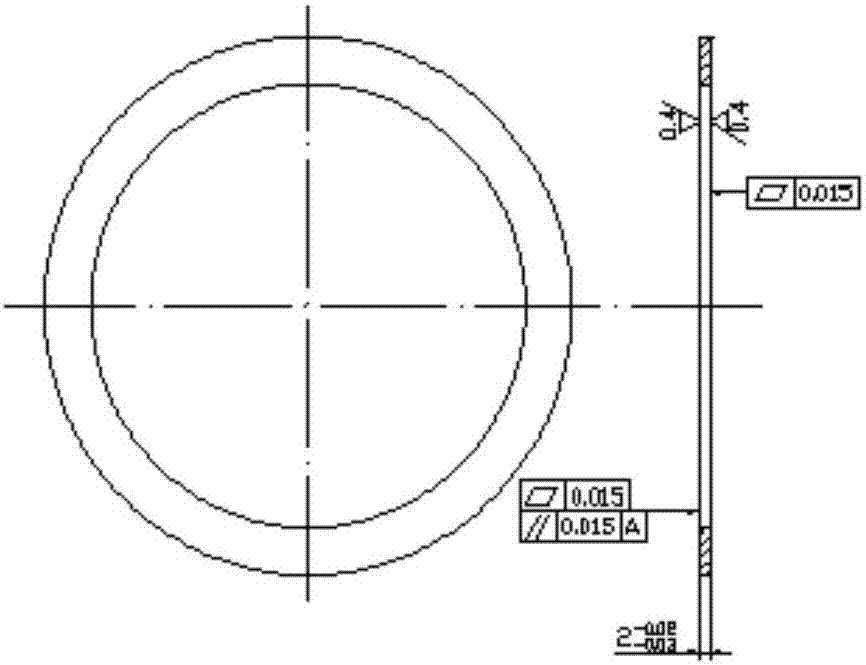
[0034] Such as figure 1 As shown, the stop ring is a product packed in a large circular ring with thin slices, and the size requirements are as follows:

[0035] thickness

[0036] Two-plane roughness <0.4mm;

[0037] Flatness<0.015mm;

[0038] Parallel difference <0.015mm.

[0039] The machining process of the above stop ring is as follows:

[0040] 0. Material selection

[0041] GCr15 bearing steel plate with a thickness of 2.5 mm needs multiple times of heating and rolling to form, and unstable stress accumulates in the plate. This stress is continuously released during the processing of large rings, causing plane warping, while thin large ring products The flatness requirement is l...


PUM

PropertyMeasurementUnit
surface smoothnessaaaaaaaaaa

Abstract

The invention belongs to the technical field of machining parts and in particular to a machining method for a stop ring. The machining method for the stop ring takes a GCr15 bearing-steel steel pipe as a raw material and the inner and outer diameters of the steel pipe are sizes of the inner and outer diameters of a stop ring blank; and then the steel pipe is cut to obtain the stop ring blank. According to the machining method for the stop ring, provided by the invention, the qualitative transition is realized by abandoning sheet material machining and replacing the sheet material machining with pipe machining, so that the utilization rate of the material is improved and material stress generated by rolling the material for a plurality of times is reduced; a cutting method is used for replacing punching so that punching machining stress of the blank is reduced and a foundation of solving a planeness problem is laid for subsequent machining; a heat treatment method is modified and the material stress, machining stress and heat treatment deformation are controlled to be minimum; and in conclusion, the problems of uncontrollable planeness, poor parallelism, poor thickness and plane roughness in an old method are solved through the machining method provided by the invention and the yield and market credibility of a product are improved.

Description

technical field [0001] The invention belongs to the technical field of mechanical processing parts, and in particular relates to a processing method of a stop ring. Background technique [0002] The stop ring is a commonly used part in mechanical parts. As an important part of the car air-conditioning compressor, its quality directly affects the noise, mechanical performance, and even life of the whole machine. [0003] The processing method of the stop ring generally includes the following steps: [0004] 1) Forming the inner and outer diameter of the stop ring; 2) Stamping and leveling the plane of the stop ring; 3) Soft grinding processing of both front and back planes; 3) Heat treatment; 4) Centerless grinding of the outer diameter of the stop ring; 5) Hard grinding of the stop ring 6) The inner diameter of the stop ring is ground on the inner die; 7) The inner diameter and outer diameter of both sides are chamfered; 8) The stability treatment eliminates the processing ...

Claims


Application Information

Patent Timeline
Patent Type & Authority Applications(China)
IPC IPC(8): B23P15/00
CPCB23P15/00
Inventor 俞立群
Owner WUJIANG SHUANGJING BEARING
Learn More