Spinning wrench device acting or moving synchronously with spinner wheel

A synchronous action, twist pliers technology, used in drilling equipment, earthwork drilling, drill pipe and other directions, can solve the problems of easy deviation, the twist roller can not be translated synchronously, etc. , the effect of shortening the distance

Pending Publication Date: 2017-10-20
SICHUAN KUNLUN GASOLINEEUM EQUIP MFG
View PDF7 Cites 5 Cited by
  • Summary
  • Abstract
  • Description
  • Claims
  • Application Information

AI Technical Summary

Problems solved by technology

[0004] The technical problem to be solved by the present invention is to provide a spinner pliers device with synchronous action or movement of the spinn

Method used


Image

  • Spinning wrench device acting or moving synchronously with spinner wheel
  • Spinning wrench device acting or moving synchronously with spinner wheel
  • Spinning wrench device acting or moving synchronously with spinner wheel

Examples


Embodiment Construction

[0035] The principles and features of the present invention are described below in conjunction with the accompanying drawings, and the examples given are only used to explain the present invention, and are not intended to limit the scope of the present invention.

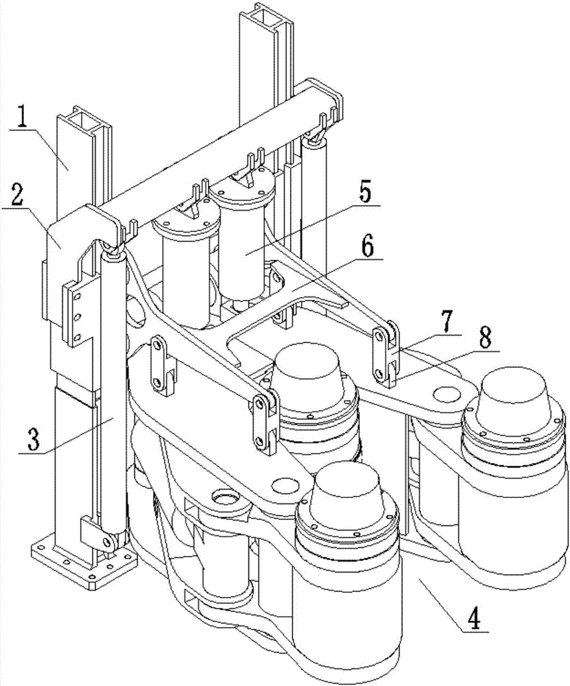
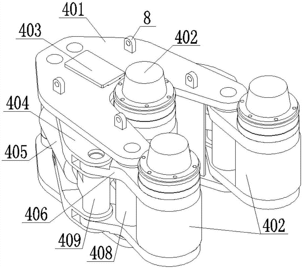
[0036] A turnbuckle pliers device with synchronous action or movement of the turnbuckle rollers, such as figure 1 , Figure 7 to Figure 9 As shown, it includes column 1, lifting tackle 2, oil cylinder 3, turnbuckle pliers 4 and hanger 6, lifting tackle 2 is slidably connected to column 1, and oil cylinder 3 is arranged between column 1 and lifting tackle 2 to drive the lifting tackle 2 Lifting movement on the column. The hanger 6 is also slidably connected on the column 1, so that the stable operation of the hanger 6 can be guaranteed when the lifting tackle 2 moves, and the lifting tackle 2 and the hanger 6 are connected by buffer devices 5 such as buffer springs or buffer hydraulic cylinders. On the one hand, it...


PUM


Abstract

The invention relates to a spinning wrench device acting or moving synchronously with a spinner wheel. The spinning wrench device comprises stand columns and a spinning wrench mounted on the stand columns. The spinning wrench comprises a rack, clamping oil cylinders, clamping arms and a rear spinning roller support, wherein two spinning assemblies are mounted on the clamping arms, and a spinning assembly is mounted on the rear spinning roller support; the rack is hinged to the middle of the clamping arms, the end portions of the clamping arms are hinged to one ends of connecting arms correspondingly, and the other ends of the connecting arms are hinged to the rear spinning roller support; one ends of the clamping oil cylinders are connected with hinged points of the clamping arms and the connecting arms correspondingly, and the other ends of the clamping oil cylinders are hinged to the rack; the connecting lines of the middles and the ends of the clamping arms are not collinear with the motion directions of the clamping oil cylinders; and a guide device is arranged between the rear spinning roller support and the rack. According to the spinning wrench device, all of the spinning assemblies can enclasp one another toward the center of a tube tool synchronously so that aligning of the tube tool is facilitated, and in the spinning process, all of the spinning assemblies are not prone to be off tracking through connective matching of the connecting arms, the clamping arms and the rear spinning roller support.

Description

technical field [0001] The invention relates to the technical field of petroleum drilling machinery and equipment, in particular to a spinner pliers device with synchronous action or movement of spinner rollers. Background technique [0002] In the automatic drilling production, the spinner pliers are currently the most advanced torque spinner equipment, which can complete the spinner connection and disassembly of drilling tools such as drill pipes and casings. During the drilling or tripping of oil drilling rigs, It is necessary to make up and break out a large number of drilling tools. The spinner tongs can play a pivotal role in reducing the labor intensity of wellhead drilling workers, improving production efficiency, and improving personnel safety. It is the most important automation in modern drilling. One of the devices. [0003] Most of the turnbuckle pliers in the prior art adopt the structure of four turnbuckle rollers. On the one hand, under the condition of the ...

Claims


Application Information

Patent Timeline
IPC IPC(8): E21B19/16
CPCE21B19/164E21B19/168
Inventor 王昌荣周克振
Owner SICHUAN KUNLUN GASOLINEEUM EQUIP MFG
Why Eureka
Try Eureka