Sealing Device For Exhaust Manifold

A sealing device and exhaust manifold technology, applied in the direction of exhaust device, sealing device of engine, expansion compensation device for pipeline, etc., can solve problems such as exhaust gas leakage, prevent external leakage, improve air tightness and The effect of sealing performance and improving marketability

Active Publication Date: 2017-10-20
HYUNDAI MOTOR CO LTD
View PDF5 Cites 2 Cited by
  • Summary
  • Abstract
  • Description
  • Claims
  • Application Information

AI Technical Summary

Problems solved by technology

[0006] However, when the conventional single-type exhaust manifold is thermally deformed at the high temperature of the exhaust gas discharged from the combustion chamber, the exhaust gas may leak from the joint joint

Method used


Image

  • Sealing Device For Exhaust Manifold
  • Sealing Device For Exhaust Manifold
  • Sealing Device For Exhaust Manifold

Examples


Embodiment Construction

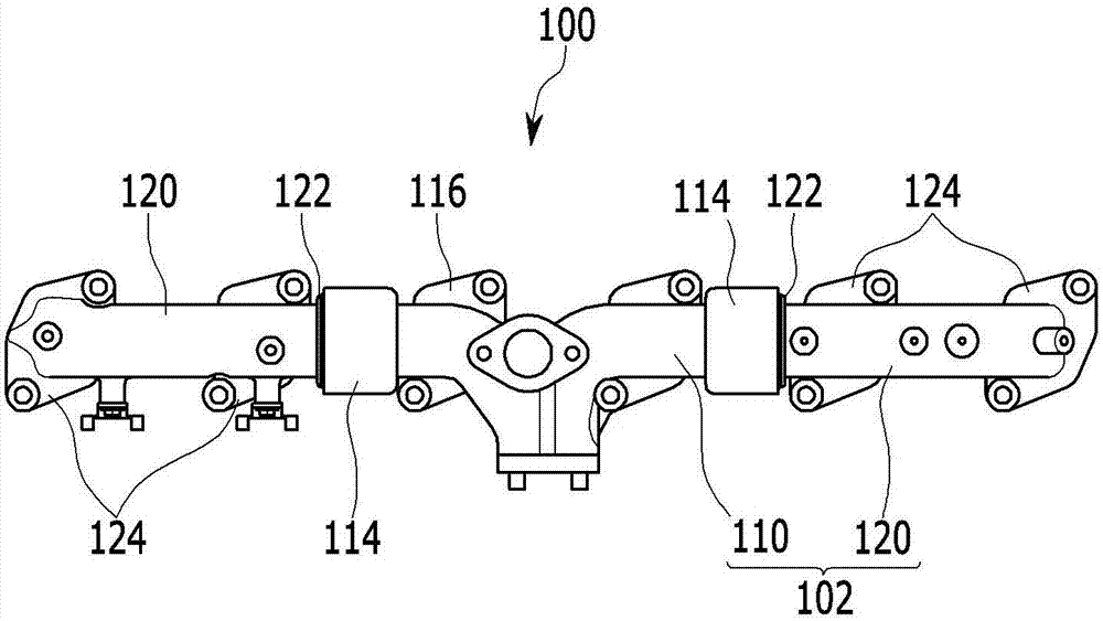
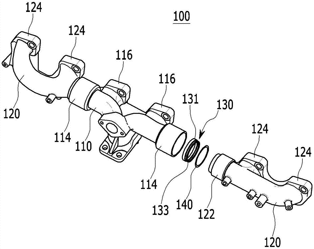
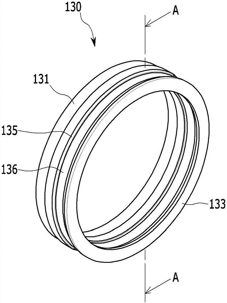
[0032] Hereinafter, exemplary embodiments of the present invention will be described in detail with reference to the accompanying drawings.

[0033] Any embodiment described in this specification and the configuration shown in the drawings are merely exemplary embodiments, and do not represent the full scope and spirit of the present invention. It should be understood that there may be various equivalents and alternatives to the exemplary embodiments. Exemplary deformation.

[0034] The drawings and descriptions should be regarded as illustrative in nature and not restrictive. Throughout the specification, the same reference numerals indicate the same elements.

[0035] In addition, in the drawings, for better understanding and ease of description, the size and thickness of each element are arbitrarily shown, and the present invention is not limited thereto, and the thickness of several parts and regions are exaggerated for clarity.

[0036] In addition, throughout the specification,...


PUM


Abstract

A sealing device for an exhaust manifold includes a main pipe having a connection portion including a mounting groove formed at an interior circumferential surface; a sub pipe having a protruding portion at one end portion, the sub pipe being coupled to the main pipe in a state in which the protruding portion is inserted into the connection portion; a valve mounted at the mounting groove within the connection portion; and a gasket interposed between the protruding portion and the valve within the connection portion.

Description

Technical field [0001] The invention relates to a sealing device for an exhaust manifold. The present invention more specifically relates to the following sealing device for exhaust manifolds, which can prevent exhaust gas from leaking between the connection parts of the exhaust manifolds formed in a separate form. Background technique [0002] Generally, the intake and exhaust systems of a vehicle supply air to the engine through an intake manifold, the air is supplied to the combustion reaction in the engine, and then the air is discharged to the outside through the exhaust manifold. [0003] The exhaust gas generated in the engine of the vehicle is exhausted through the exhaust system, and this exhaust system includes an exhaust line that introduces the exhaust gas to the rear side of the vehicle and a muffler installed on the exhaust line to attenuate exhaust noise. [0004] An exhaust manifold used to guide the exhaust gas discharged from each combustion chamber to the exhaust ...

Claims


Application Information

Patent Timeline
Patent Type & Authority Applications(China)
IPC IPC(8): F01N13/10F01N13/18F02F11/00
CPCF01N13/10F01N13/1827F01N13/1844F02F11/00F16L23/24F16L51/00F01N13/1811F01N2290/08F16J15/021F16J15/08F16K31/002F16L21/02
Inventor 李载真
Owner HYUNDAI MOTOR CO LTD
Why Eureka
Try Eureka