Thermal-sensing type valve mechanism

A valve mechanism and temperature-sensing technology, applied in the field of temperature-sensing valve mechanisms, can solve problems such as cost increase, and achieve the effects of reducing assembly man-hours, absorbing manufacturing errors, and accurate hydraulic characteristics

Active Publication Date: 2017-10-20
YAMADA SEISAKUSHO KK
View PDF6 Cites 0 Cited by
  • Summary
  • Abstract
  • Description
  • Claims
  • Application Information

AI Technical Summary

Problems solved by technology

[0008] The temperature sensing valve (12) is a small part, and the cylinder block (13) is a medium or large part, so the cost for confirming the performance of the valve mechanism increases

Method used


Image

  • Thermal-sensing type valve mechanism
  • Thermal-sensing type valve mechanism
  • Thermal-sensing type valve mechanism

Examples


Embodiment

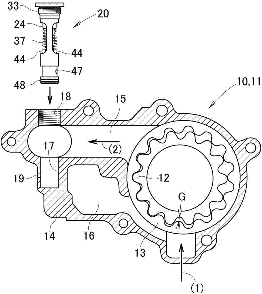
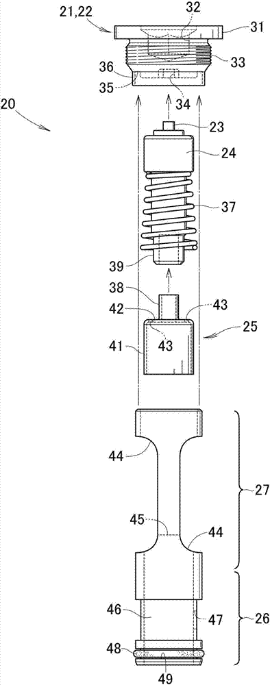
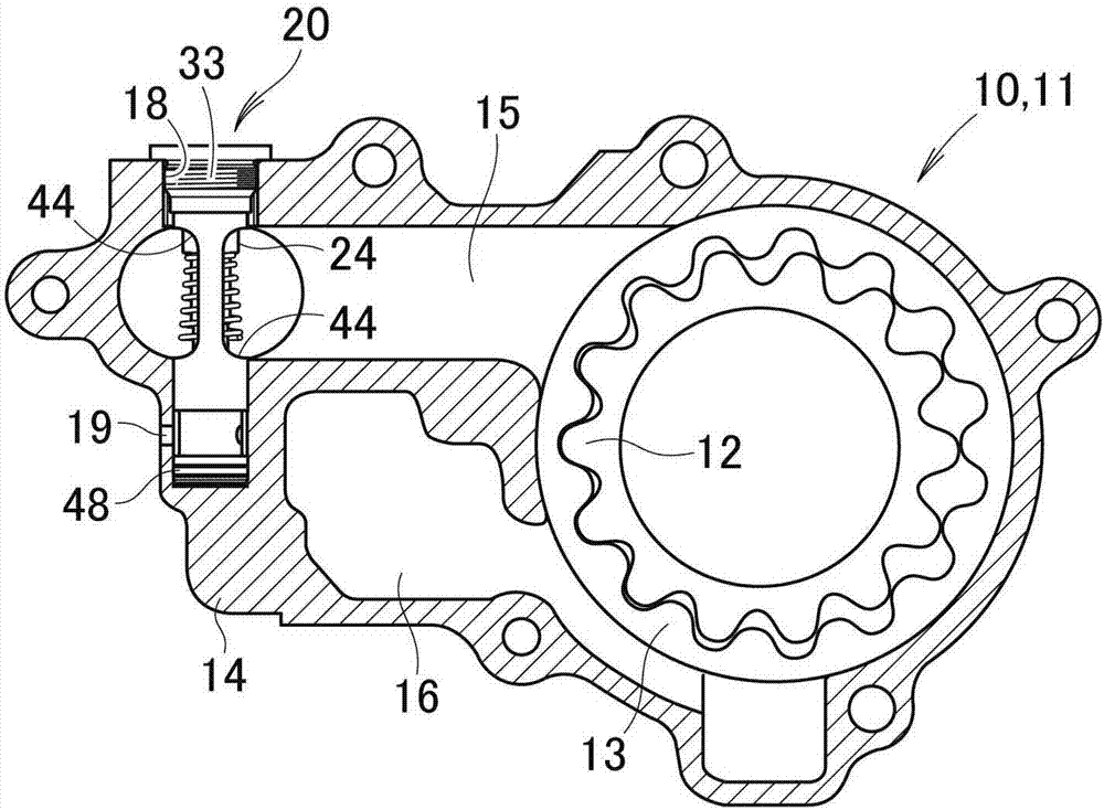
[0062] exist figure 1 Here, an example in which the temperature-sensitive valve mechanism 20 of the present invention is detachably attached to the oil pump 11 as the structure 10 will be described.

[0063] Such as figure 1 As shown, an oil pump 11 as a structure 10 is composed of an internal gear 12 , an external gear 13 , and a pump case 14 that accommodates these gears 12 and 13 . When the internal gear 12 is rotated by a part of the power of the engine, the external gear 13 is rotated interlockingly. During this rotation, the volume of the gap G between the gears 12, 13 changes, and due to this change, lubricating oil is sucked in and pressurized as indicated by the arrow (1), and is compressed as indicated by the arrow (2). was discharged.

[0064] The pump housing 14 is provided with a main oil passage 15 as an oil passage, and a return oil passage 16 is provided substantially parallel to the main oil passage 15 . When the hydraulic pressure in the main oil passag...


PUM


Abstract

The invention provides a thermal-sensing type valve mechanism which can confirm thermal performance with low cost. A pump shell (14) is provided with a main oil path (15), and a return oil path (16) parallel to the main oil path (15) substantially is arranged. The pump shell (14) is provided with a valve insertion hole (17) which transecting the main oil path (15), with the tail end reaching the vicinity of the return oil path (16). The valve insertion hole (17) is provided with an internal thread (18) at the hole opening and is provided with a through hole (19) leading to the outside of the pump shell (14) at the tail end. The thermal-sensing type valve mechanism (20) can be inserted in the valve insertion hole (17) any time. In the prior art, a thermal-sensing type valve mechanism and a pump shell need to be carried to a liquid tank or constant temperature tank together. The invention solves the problem. People only need to carry the small and light thermal-sensing type valve mechanism to the liquid tank or constant temperature tank. The thermal-sensing type valve mechanism can determine thermal performance with low cost.

Description

technical field [0001] The present invention relates to a temperature-sensitive valve mechanism that is installed in a structure (pump casing, cylinder, etc.) Outside the oil circuit. Background technique [0002] There is known a thermosensitive valve which is installed in the cylinder block of an internal combustion engine and releases the lubricating oil out of the oil path according to the temperature of the lubricating oil flowing in the oil path (for example, refer to Patent Document 1( Figure 7 )). [0003] As in Patent Document 1 Figure 7 As shown, in the cylinder (13) (numbers in parentheses indicate the reference numerals described in Patent Document 1. The same applies below) are provided with a lubricating oil supply passage (6b), a bypass through hole (51), a through hole (61) and temperature sensing valve (12). [0004] The bypass through hole (51) is blocked by the upper surface of the temperature sensing valve (12). When the oil temperature decreases, th...

Claims


Application Information

Patent Timeline
Patent Type & Authority Applications(China)
IPC IPC(8): F04C15/06F04C14/24F01M1/16F16K3/26F16K27/04F16K31/68
CPCF01M1/16F04C14/24F04C15/06F16K3/26F16K27/041F16K31/002
Inventor 宫岛淳一庄司一夫加藤悠也
Owner YAMADA SEISAKUSHO KK
Why Eureka
Try Eureka