
Particle temperature and particle motion synchronous measuring apparatus and method

A technology of particle temperature and particle movement, which is applied in the direction of measuring devices, particle and sedimentation analysis, individual particle analysis, etc., can solve the problems of inability to measure particle temperature, small number of particles, and inability to measure particle temperature, etc., and achieve fast measurement speed and resolution The effect of high efficiency and improved accuracy

Active Publication Date: 2017-10-20
UNIV OF SHANGHAI FOR SCI & TECH
View PDF4 Cites 2 Cited by
  • Summary
  • Abstract
  • Description
  • Claims
  • Application Information

AI Technical Summary

Problems solved by technology

[0004] At present, there are many technologies for researching and detecting particle temperature and particle motion, such as particle image velocimetry and particle tracking velocimetry, but the above-mentioned technologies are based on image processing methods, which can only measure the surface movement of particle groups, and cannot simultaneously measure particle temperature.
In addition, technologies such as positron emission particle tracking, X-ray tomography, and magnetic resonance imaging all obtain the movement of particle groups by tracking special particles added to particle groups, but the number of particles measured by these methods is small, and Not the particles that were originally measured, and the particle temperature cannot be measured

Method used


Image

  • Particle temperature and particle motion synchronous measuring apparatus and method
  • Particle temperature and particle motion synchronous measuring apparatus and method
  • Particle temperature and particle motion synchronous measuring apparatus and method

Examples


Embodiment Construction

[0035] In order to make the technical means and effects realized by the present invention easy to understand, the present invention will be described in detail below in conjunction with the embodiments and accompanying drawings.

[0036]

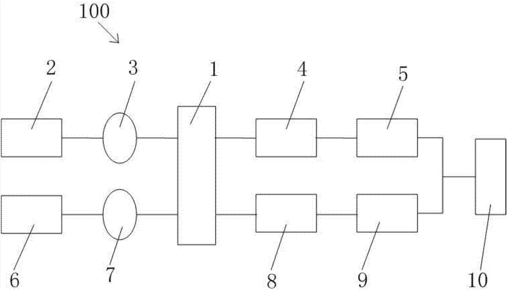
[0037] figure 1 It is a schematic diagram of the particle temperature and particle motion synchronous measurement device in the embodiment of the present invention.

[0038] The particle temperature and particle motion synchronous measurement device 100 is used to measure the particle temperature in different areas of the particle flow, and obtain the particle motion in different areas at the same time, including: a sample cell 1, a first laser emitter 2, a first concave lens 3, a first A bandpass filter 4 , a first signal collection component 5 , a second laser emitter 6 , a second concave lens 7 , a second bandpass filter 8 , a second signal collection component 9 and a computer 10 .

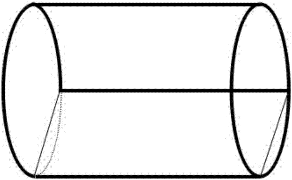
[0039] figure 2 It is a structural sc...


PUM


Abstract

The invention provides a particle temperature and particle motion synchronous measuring apparatus, which is used for measuring a particle temperature of a particle flow in different areas, and obtaining a particle motion condition of different areas. The particle temperature and particle motion synchronous measuring apparatus is characterized by comprising a sample pool which is used for storing particles and driving the particles to roll; a first laser transmitter which is used for emitting first laser; a first concave lens which is used for diffusing first laser and projecting the first laser onto a surface layer of the particle to form first signal light; a first band-pass optical filter which is used for allowing the light of a particular waveband in the first signal light to pass; a first signal acquisition component which is used for acquiring the first signal light to obtain a first speckle image; a second laser transmitter; a second concave lens; a second band-pass optical filter; a second signal acquisition component which is used for acquiring a second speckle image; and a computer which is used for storing, converting and calculating the first speckle image and the second speckle image to obtain a curve graph of the particle temperature and curve graph of the particle motion over time in different areas.

Description

technical field [0001] The invention relates to a device and method for synchronously measuring particle temperature and particle movement. Background technique [0002] Particulate matter is ubiquitous in nature, daily life, production and technology, for example: sand, soil, floating water, snow, etc. in nature, grain, white sugar, salt, etc. in daily life, coal, ore in production and technology and pharmaceuticals and chemicals. Therefore, the complex physical properties exhibited by particulate matter have been extensively studied, among which the most studied physical properties are particle temperature and particle motion of particulate matter. [0003] Collisions between particles will generate random fluctuations and generate heat. Therefore, the particle temperature (granular temperature, <δv>) is used to indicate the degree of activity of the random movement of particles. The relationship between particle temperature and particle motion is as follows Wher...

Claims


Application Information

Patent Timeline
IPC IPC(8): G01N15/10
CPCG01N15/10
Inventor 侯鹏杨晖李然
Owner UNIV OF SHANGHAI FOR SCI & TECH
Learn More