On-line distance measurement method of protection fault information management system

A technology of management system and distance measurement method, which is applied to fault location, fault detection according to conductor type, etc., can solve the problem of low timeliness of fault recording data, and achieve the effect of improving timeliness

Active Publication Date: 2017-10-20
ZHONGSHAN POWER SUPPLY BUREAU OF GUANGDONG POWER GRID
5 Cites 13 Cited by

AI-Extracted Technical Summary

Problems solved by technology

[0007] The present invention provides an online ranging method for protecting the fault information management system in order to solve the t...

Abstract

The present invention relates to an on-line distance measurement method of a protection fault information management system. The method comprises the following steps that: S1, after a power grid malfunctions, a fault line is judged according to remote signaling shift, SOE and protection action signals; S2, the recording file of a specified fault recorder of a two-side plant station to which the fault line belongs is called; S3, a specific fault time point and a corresponding failure device are determined according to the phase current sudden change quantity of the recording file, and eight analog quantity channels, namely three-phase voltages, a zero-sequence voltage, three-phase current and zero-sequence current of the failure device are further determined; S4, as for disperse sampling points of a cyclic wave before the fault and a cyclic wave after the fault, the complex values of the three-phase voltages, the zero-sequence voltage, three-phase current and zero-sequence current before and after fault are calculated through using a differential Fourier series algorithm according to the fault time point and the eight analog quantity channels; S5, positive-sequence, negative-sequence and zero-sequence current values after the fault are calculated through phase sequence conversion, and a fault phase is determined through the comparative analysis of sequence current fault components; and S6, after the fault phase is determined, distance measurement calculation at a single end side or two end sides is performed.

Application Domain

Technology Topic

Image

  • On-line distance measurement method of protection fault information management system
  • On-line distance measurement method of protection fault information management system
  • On-line distance measurement method of protection fault information management system

Examples

  • Experimental program(1)

Example Embodiment

[0023] Example 1
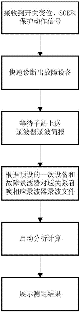
[0024] Such as figure 1 As shown, an online ranging method for protecting a fault information management system includes the following steps:
[0025] S1. After the power grid fails, determine the faulty line according to the remote signal displacement, SOE and protection action signals;
[0026] S2. Summon the recording file of the designated wave recorder of the plant on both sides of the fault line;
[0027] S3. Determine the specific fault time and the corresponding faulty equipment according to the phase current mutation recorded in the wave file, and further determine the three-phase voltage, zero sequence voltage, three-phase current and zero sequence current of the faulty equipment, totaling 8 analog channels ;
[0028] S4. Based on the determined fault time and 8 analog channels, the differential Fourier series algorithm is applied to the discrete sampling points of one cycle before the fault and one cycle after the fault to calculate the three-phase voltage, zero sequence voltage and three-phase current before and after the fault , The complex value of the zero sequence current;
[0029] S5. Calculate the positive sequence, negative sequence and zero sequence current values ​​after the fault through phase sequence conversion, and determine the fault phase by comparing and analyzing the sequence current fault components;
[0030] S6. After the fault phase is determined, the single-ended or double-ended ranging calculation is performed.
[0031] In the specific implementation process, such as figure 2 As shown, the specific process of determining the fault phase in step S5 is as follows:
[0032] S51. Determine whether there is a zero-sequence component, if yes, go to step S52, otherwise go to step S58;
[0033] S52. Judge whether the phase angle of A phase is 0 degrees, if yes, confirm the fault phase as A phase fault, otherwise go to step S53;
[0034] S53. Judge whether the phase angle of phase A is 180 degrees, if yes, confirm the fault phase as an indirect fault of phase B and phase C; otherwise, go to step S54;
[0035] S54. Judge whether the phase angle of phase B is 0 degrees, if yes, confirm the fault phase as phase B fault, otherwise go to step S55;
[0036] S55. Judge whether the phase angle of phase B is 180 degrees, if yes, confirm the fault phase as an indirect fault of phase C and phase A, otherwise go to step S56;
[0037] S56. Judge whether the phase angle of phase C is 0 degrees, if yes, confirm the fault phase as a phase C fault, otherwise go to step S57;
[0038] S57. Judge whether the phase angle of phase C is 180 degrees, and if so, confirm the fault phase as an indirect fault of phase A and phase B, otherwise the output fault phase determination fails;
[0039] S58. Determine whether there is a positive sequence current of phase A and a negative sequence current of phase A, if yes, confirm the fault phase as a fault between phase B and phase C; otherwise, go to step S59;
[0040] S59. Judge whether there are B-phase positive sequence current and B-phase negative sequence current, if yes, confirm the fault phase as a fault between phase C and A; otherwise, go to step S60;
[0041] S60. Judge whether there is a positive sequence current of phase C and a negative sequence current of phase C. If so, the fault phase is confirmed as a phase A and B phase fault; otherwise, the output fault phase determination fails.
[0042] image 3 A schematic diagram of a single-phase system. Suppose the m terminal is the measuring terminal, the measured impedance can be expressed as
[0043]
[0044] In the formula: Z is the impedance per unit length of the line; D mF Is the distance from end m to the fault point F; Is the voltage and current measured at the m terminal; R F Is the transition resistance at the fault point; ΔZ is the measurement error, Is the short-circuit current at the fault point.
[0045] The following relationship exists between the fault point and the fault component of the m-terminal current
[0046]
[0047] among them Is the load current and fault component at end m; Is the current at the fault point; C m Is the current distribution coefficient at the m terminal. The impedance method ranging principle is as follows:
[0048] According to formula (1), we can get
[0049]
[0050] Take the imaginary part at both ends of equation (3) to get
[0051]
[0052] among them X is the unit reactance of the line, and R is the unit resistance of the line.
[0053] The ranging principle of solving complex equation method is as follows:
[0054] According to formula (1) and (2), we can get
[0055]
[0056] Take the imaginary part at both ends of equation (5) to get
[0057]
[0058] among them for The conjugate complex number.
[0059] From equation (5), it can be deduced that when a single-phase short circuit is grounded, the general formula
[0060]
[0061] Where: Is the fault phase voltage and current. p represents the short-circuit ground phase, which is A or B or C. Is the current fault component of the m terminal. j represents positive sequence, negative sequence, or zero sequence, j=1, 2, 0. for The conjugate complex number.
[0062] The algorithm for two-phase short circuit is
[0063]
[0064] Where: Is the voltage difference and current difference of the two faulty phases; The non-fault phase is the negative sequence current of the special phase. for The conjugate complex number.
[0065] The ranging algorithm when two phases are short-circuited to ground is
[0066]
[0067] Where: The non-fault phase is the positive sequence fault component current of the special phase. for The conjugate complex number.
[0068] The algorithm for three-phase short circuit is
[0069]
[0070] Where: Is the fault component of any phase current, where p is A or B or C. for The conjugate complex number.
[0071] Double-ended ranging mainly uses a binary search method based on fault components that does not require synchronization of double-ended data. Different calculation methods can be used according to different line lengths. For short lines, a lumped parameter model that does not need to consider distributed capacitance is adopted. The basic principle is as follows:
[0072] according to image 3 It can be seen that the fault point voltage is:
[0073]
[0074]
[0075] When the amplitude of formula (11) and the amplitude of formula (12) infinitely approach the same, D mF Is the fault location value.
[0076] For long-distance lines, because the distributed capacitance cannot be ignored, a distributed parameter model is required. The basic principle is as follows:
[0077] according to image 3 It can be seen that the fault point voltage is:
[0078]
[0079]
[0080] Where is the propagation constant, Z c Is the wave impedance. When the amplitude of equation (13) and the amplitude of equation (14) infinitely approach the same, D mF Is the fault location value.

PUM

no PUM

Description & Claims & Application Information

We can also present the details of the Description, Claims and Application information to help users get a comprehensive understanding of the technical details of the patent, such as background art, summary of invention, brief description of drawings, description of embodiments, and other original content. On the other hand, users can also determine the specific scope of protection of the technology through the list of claims; as well as understand the changes in the life cycle of the technology with the presentation of the patent timeline. Login to view more.

Similar technology patents

User portrait based marketing method, device and system

InactiveCN107274201AImprove timelinessMarketingUser deviceEvent trigger
Owner:BEIJING DIDI INFINITY TECH & DEV

Classification and recommendation of technical efficacy words

Why Eureka
Try Eureka