Industrial control computer heat dissipation device

A heat dissipation device and industrial control technology, which is applied in computing, instruments, electrical digital data processing, etc., can solve the problems of easy ash falling, the main engine cannot effectively dissipate heat, etc., and achieve the effect of labor saving and convenient placement

Inactive Publication Date: 2017-10-20
湖州佳灏信息技术有限公司
View PDF0 Cites 9 Cited by
  • Summary
  • Abstract
  • Description
  • Claims
  • Application Information

AI Technical Summary

Problems solved by technology

[0006] In order to overcome the shortcomings in the prior art that the main engine cannot be effectively dissipated after being used for a long time, and it is easy to ash when i...

Method used


Image

  • Industrial control computer heat dissipation device
  • Industrial control computer heat dissipation device
  • Industrial control computer heat dissipation device

Examples


Embodiment 1

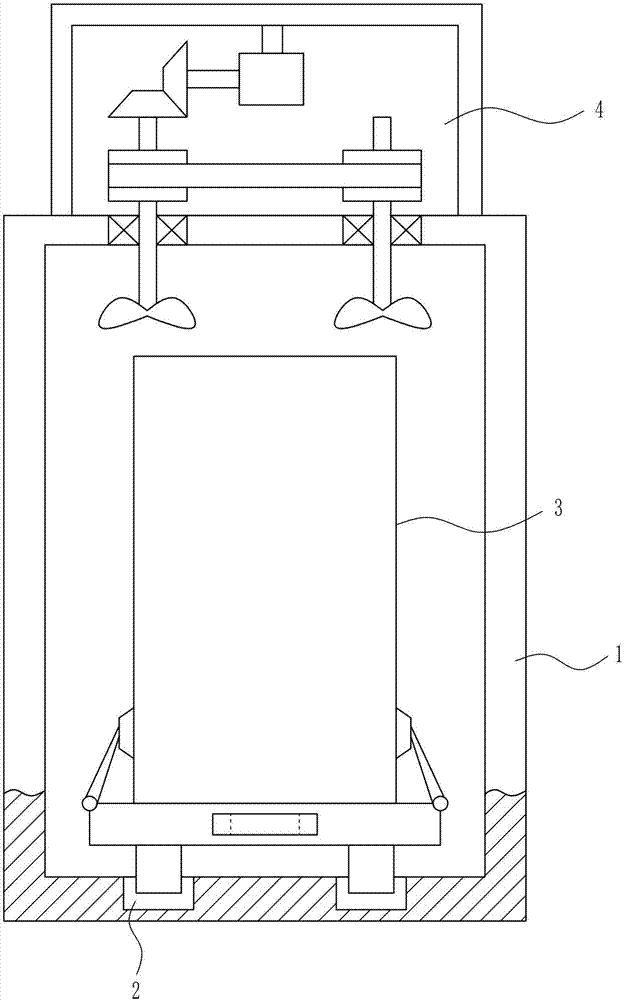
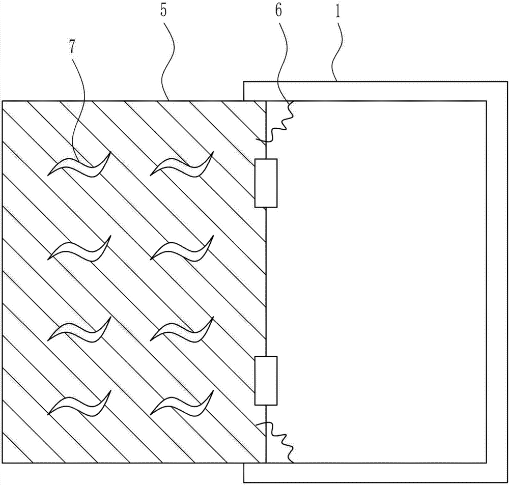
[0033] A computer cooling device for industrial control, such as Figure 1-6 As shown, it includes a placement box 1, a moving mechanism 2, a cooling mechanism 4, a door 5 and a first spring 6. The left side of the front wall is connected with a box door 5 by means of a hinge connection, and the first spring 6 is symmetrically connected between the inside of the box door 5 and the inside of the storage box 1, and S-shaped holes 7 are evenly arranged on the box door 5 .

Embodiment 2

[0035] A computer cooling device for industrial control, such as Figure 1-6As shown, it includes a placement box 1, a moving mechanism 2, a cooling mechanism 4, a door 5 and a first spring 6. The left side of the front wall is connected with a box door 5 by means of a hinge connection, and the first spring 6 is symmetrically connected between the inside of the box door 5 and the inside of the storage box 1, and S-shaped holes 7 are evenly arranged on the box door 5 .

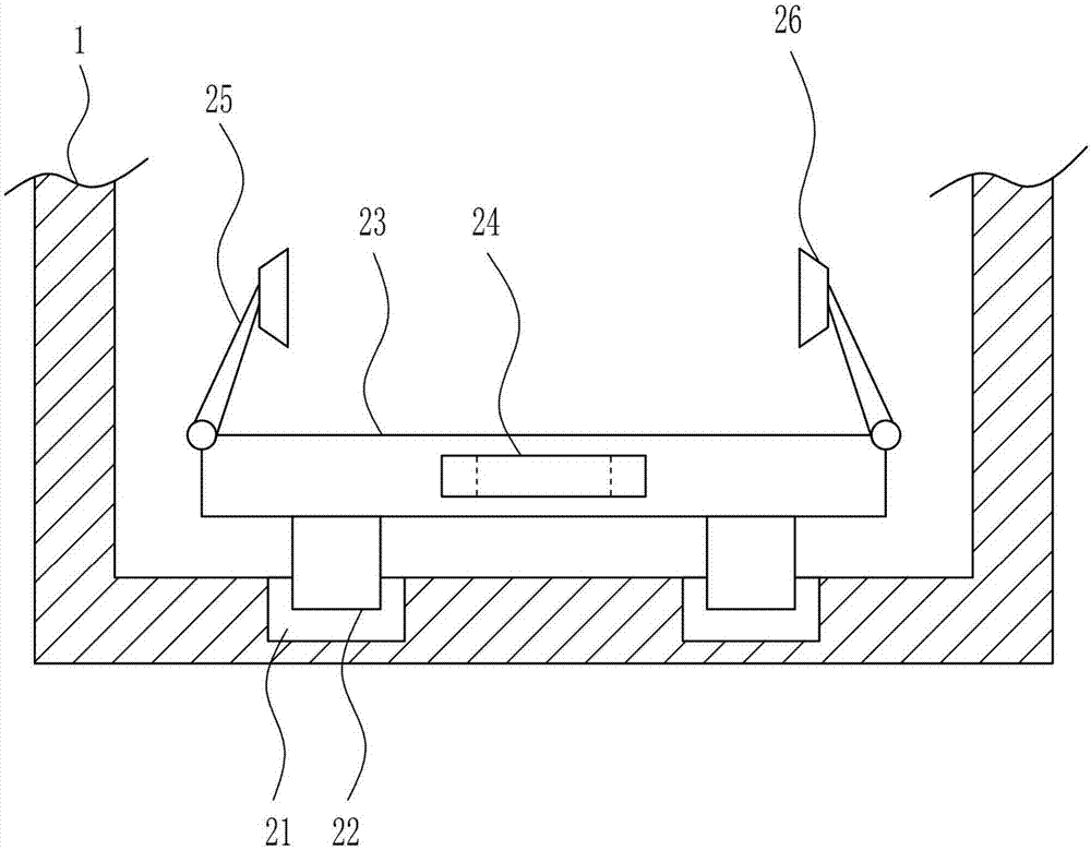
[0036] The moving mechanism 2 includes a slide rail 21, a slide block 22, a placement plate 23, a handle 24, a first rotating rod 25 and a suction cup 26, and the bottom of the placement box 1 is symmetrically connected with a slide rail 21, and the slide rail 21 is slidably connected with a slide rail. Block 22, slide rail 21 cooperates with slide block 22, slide block 22 top is connected with place plate 23, place plate 23 front wall middle part is connected with handle 24, and place plate 23 left and right s...

Embodiment 3

[0038] A computer cooling device for industrial control, such as Figure 1-6 As shown, it includes a placement box 1, a moving mechanism 2, a cooling mechanism 4, a door 5 and a first spring 6. The left side of the front wall is connected with a box door 5 by means of a hinge connection, and the first spring 6 is symmetrically connected between the inside of the box door 5 and the inside of the storage box 1, and S-shaped holes 7 are evenly arranged on the box door 5 .

[0039] The moving mechanism 2 includes a slide rail 21, a slide block 22, a placement plate 23, a handle 24, a first rotating rod 25 and a suction cup 26, and the bottom of the placement box 1 is symmetrically connected with a slide rail 21, and the slide rail 21 is slidably connected with a slide rail. Block 22, slide rail 21 cooperates with slide block 22, slide block 22 top is connected with place plate 23, place plate 23 front wall middle part is connected with handle 24, and place plate 23 left and right ...


PUM


Abstract

The invention relates to a cooling device, in particular to a computer cooling device for industrial control. The technical problem to be solved by the present invention is to provide an industrial control computer cooling device capable of effectively dissipating heat while ensuring that the machine does not fall into dust. In order to solve the above technical problems, the present invention provides such an industrial control computer cooling device, including a storage box, etc.; The mode of hinge connection is connected with box door, and the first spring is symmetrically connected between the inside of the box door and the inside of the storage box, and S-shaped holes are evenly opened on the box door. In the present invention, the box door is first opened, the handle drives the placing plate to move outward, the computer host is placed on the placing plate and fixed, the box door is closed, and the box door is fixed under the action of the magnet and the inserting rod.

Description

technical field [0001] The invention relates to a cooling device, in particular to a computer cooling device for industrial control. Background technique [0002] Industrial control refers to industrial automation control, which is mainly realized by a combination of electronics, machinery, and software. That is industrial control, or factory automation control. It mainly refers to the use of computer technology, microelectronics technology, and electrical means to make the production and manufacturing process of the factory more automated, efficient, precise, and controllable and visible. [0003] The computer host refers to the container used to place the motherboard and other major components in the computer hardware system. Usually includes CPU, memory, hard disk, optical drive, power supply, and other input and output controllers and interfaces, such as USB controllers, graphics cards, network cards, sound cards, and so on. Usually, the host itself (after installing ...

Claims


Application Information

Patent Timeline
IPC IPC(8): G06F1/20G06F1/18
CPCG06F1/20G06F1/181
Inventor 施欢权
Owner 湖州佳灏信息技术有限公司
Why Eureka
Try Eureka