Chopper structure

A chopping knife and arc-shaped technology, which is applied in the field of semiconductor packaging, can solve problems such as scratches on welding wires and affect the welding quality of semiconductor products, and achieve the effects of not being easy to detach, improving welding force, and avoiding scratches

Active Publication Date: 2017-10-20
CHAOZHOU THREE CIRCLE GRP
View PDF4 Cites 4 Cited by
  • Summary
  • Abstract
  • Description
  • Claims
  • Application Information

AI Technical Summary

Problems solved by technology

[0004] For the traditional riving knife, when the welding wire moves relative to the wire hole and elongates relative to the end of the riving knife, the welding wire will be scratched, which will affect the welding quality of semiconductor products

Method used


Image

  • Chopper structure
  • Chopper structure
  • Chopper structure

Examples


Embodiment 1

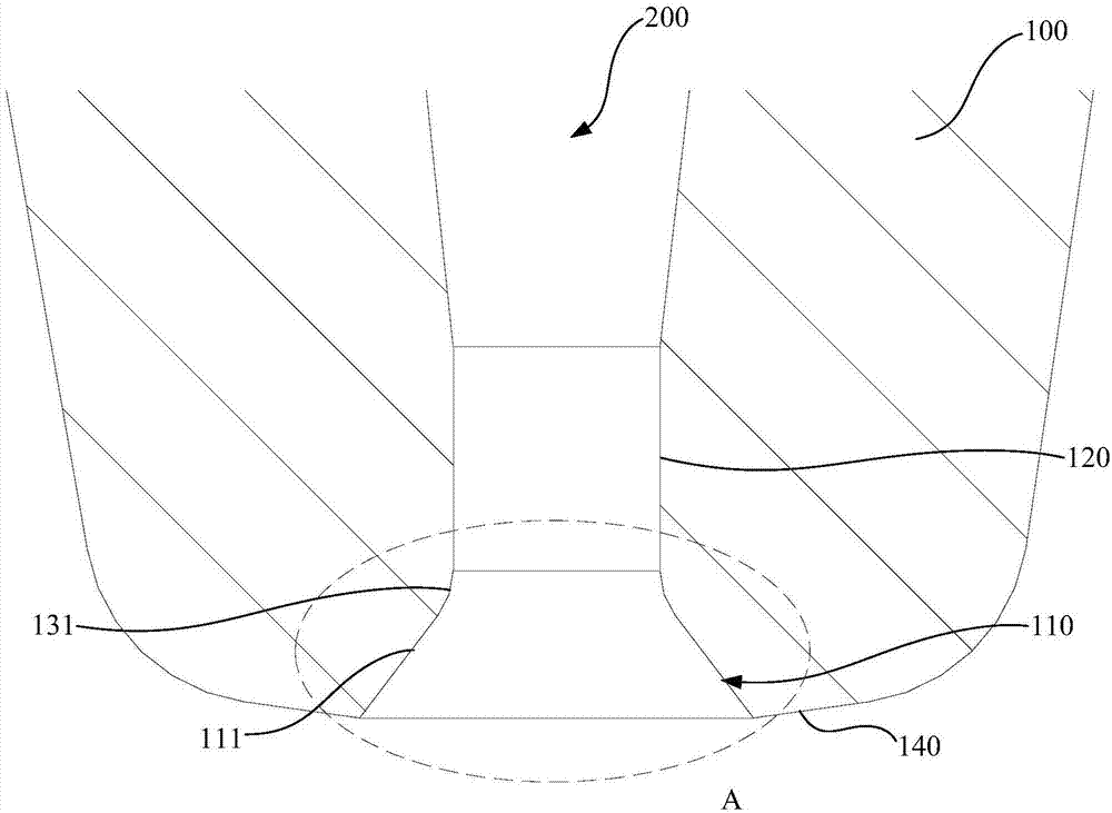
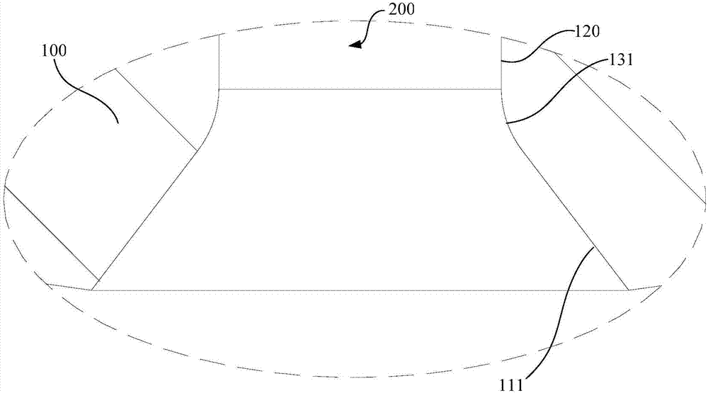
[0028] see also figure 1 with figure 2 , the tapered wall 110 includes a first tapered wall 111, the first tapered wall 111 is close to the end of the rivier body 100, the top end of the first arc transition wall 131 is connected with the bottom end of the inner cavity wall 120, and the first arc transition The bottom end of the wall 131 is connected with the top end of the first tapered wall 111 . The first cone wall 111 is surrounded by an inner chamfer (that is, a single inner chamfer). The inner cavity wall 120 defines the inner hole, and the first arc-shaped transition wall 131 defines the transition hole between the inner chamfer and the inner hole.

[0029] The first arc-shaped transition wall 131 is arc-shaped, and its radius is R, wherein the value range of R is: 2 μm ≤ R ≤ 60 μm. In this embodiment, the value of the radius R of the first arc-shaped transition wall 131 is 30 μm. Certainly, there are other value points, for example, the value of the radius R of th...

Embodiment 2

[0033] refer to Figure 5 , the tapered wall 110 includes a second tapered wall 112 and a third tapered wall 113 . The second cone wall 112 is close to the end of the riving tool body 100, the third cone wall 113 is coaxially arranged with the second cone wall 112 and the inner cavity wall 120, and the third cone wall 113 is located between the second cone wall 112 and the inner cavity wall 120 between. Specifically, the bottom end of the inner cavity wall 120 is connected to the top end of the first arc-shaped transition wall 131, the bottom end of the first arc-shaped transition wall 131 is connected to the top end of the third cone wall 113, and the bottom end of the third cone wall 113 It is connected with the top end of the second cone wall 112 .

[0034] In fact, the second cone wall 112 and the third cone wall 113 are respectively surrounded by an inner chamfer, that is, a double inner chamfer. Due to the existence of the double inner chamfer, the scratching of the ou...

Embodiment 3

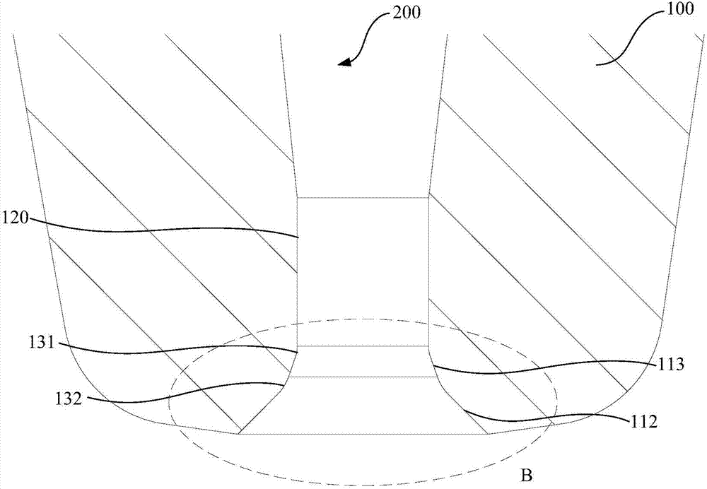
[0038] see also image 3 and Figure 4 , the tapered wall 110 includes a second tapered wall 112 , a third tapered wall 113 and a second arc-shaped transition wall 132 . The second cone wall 112 is close to the end of the riving tool body 100, the third cone wall 113 is coaxially arranged with the second cone wall 112 and the inner cavity wall 120, and the third cone wall 113 is located between the second cone wall 112 and the inner cavity wall 120 between. Specifically, the bottom end of the inner cavity wall 120 is connected to the top end of the first arc-shaped transition wall 131, the bottom end of the first arc-shaped transition wall 131 is connected to the top end of the third cone wall 113, and the bottom end of the third cone wall 113 It is connected with the top end of the second arc-shaped transition wall 132 , and the bottom end of the second arc-shaped transition wall 132 is connected with the top end of the second tapered wall 112 .

[0039] Since the second a...


PUM

PropertyMeasurementUnit
Radiusaaaaaaaaaa

Abstract

The invention relates to a chopper structure which comprises a chopper body. The copper body is internally provided with a conical wall of which the central axis is superposed with that of the chopper body, wherein the conical wall is next to the end of the copper body, an inner chamber wall which is coaxially arranged with the conical wall, and a first arc-shaped transition wall which is connected with the conical wall and the inner chamber wall. The conical wall, the inner chamber wall and the first arc-shaped transition wall form a wire passing through hole for passing of a solder wire. In a movement process of the solder wire relative to the wire passing through hole, because the first arc-shaped transition wall is connected between the conical wall and the inner chamber wall, a closed angle at a connection part between the conical wall and the inner chamber wall is eliminated, and smooth transition of the connection between the conical wall and the inner chamber wall is realized, thereby effectively preventing scratch of the closed angle to the surface of the solder wire, ensuring high mechanical strength of the solder wire, realizing no easy pulling breakage or fatigue breakage of the solder wire by an external impact force or an alternate stress, and ensuring high soldering quality of the solder wire.

Description

technical field [0001] The invention relates to the technical field of semiconductor packaging, in particular to a capillary structure. Background technique [0002] In the production process of semiconductor integrated circuits, it is usually necessary to connect the semiconductor bare chip pads with the I / O leads of the microelectronic package or the metal wiring pads on the substrate with metal filaments (welding wires). [0003] Generally, the welding wire is passed through the wire hole of the chopper, and the welding wire is welded by thermocompression bonding or ultrasonic bonding (that is, under the action of heating, pressure or friction, the welding wire and the welding area The atoms on the contact surface reach the range of atomic attraction and are welded). Specifically, the welding wire is bonded with the first welding station to form a first bonding point (that is, one end of the welding wire has been fixed at the first welding station, and the fixed end of t...

Claims


Application Information

Patent Timeline
IPC IPC(8): H01L21/60
CPCH01L24/78H01L2224/78611H01L2224/48091H01L2224/48465H01L2224/78303H01L2224/859H01L2924/00014
Inventor 邱基华
Owner CHAOZHOU THREE CIRCLE GRP
Why Eureka
Try Eureka