Welding cleaver and preparation method thereof

A rivet and knife tip technology is applied in the field of welding rivets and their preparation, which can solve the problems of shortening the life of the ribbing knife, increasing energy consumption, and metal residues, reducing energy loss, improving transmission efficiency, and simplifying processing conditions. Effect

Active Publication Date: 2017-10-20
CHAOZHOU THREE CIRCLE GRP
View PDF5 Cites 12 Cited by
  • Summary
  • Abstract
  • Description
  • Claims
  • Application Information

AI Technical Summary

Problems solved by technology

The above welding chopper has the following defects: 1) The influence of the structure on the conduction efficiency of ultrasonic energy is not fully considered, so that the conduction efficiency of ultrasonic energy is low and energy consumption is increased; 2) The processing of the three-stage coupling structure is difficult ; 3) Designing multiple grooves at the inner chamfer does not improve the ultrasonic transmission efficiency significantly; 4) The metal residue is serious during the welding process of the groove structure, and the service life of the chopper is greatly reduced; 5) The width and depth of the groove are difficult to control, and the processing Imperfect means

Method used


Image

  • Welding cleaver and preparation method thereof
  • Welding cleaver and preparation method thereof
  • Welding cleaver and preparation method thereof

Examples


Embodiment 1

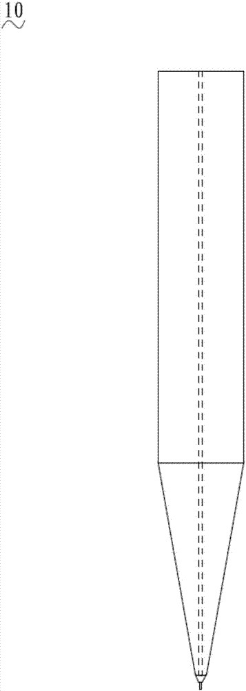
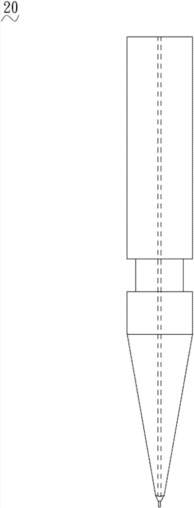
[0037] see Figure 4 to Figure 6 , the welding capillary 40 of the first embodiment of the present invention includes a connecting portion 41 and a knife mouth portion 42 connecting the connecting portion 41, the middle part of the welding capillary 40 is provided with a passage 43, and the passage 43 extends from the top of the connecting portion 41 To the bottom of the knife mouth 42 , the passage 43 communicates with the connecting portion 41 and the center of the knife mouth 42 , so that the ultrasonic waves can be transmitted from the top of the connecting portion 41 to the bottom of the knife mouth 42 .

[0038] Further, the connecting portion 41 is cylindrical for connecting the ultrasonic transducer, and the mouth portion 42 is conical.

[0039] In this embodiment, passage 43 includes cylindrical groove 411 and tapered groove 412 connected with cylindrical groove 411. The diameter of cylindrical groove 411 is greater than the diameter of one end of tapered groove 412 c...

Embodiment 2

[0049] see Figure 4 and Figure 7 The external structure of the connecting portion 41 and the tip portion 42 of the welding capillary 420 of this embodiment is the same as that of the welding capillary 40 of the first embodiment. The difference is that the passageway 43 of the present embodiment includes a cylindrical groove 421 and a tapered groove 422 connected to the cylindrical groove 421. The diameter of the cylindrical groove 421 is equal to the diameter of one end of the tapered groove 422 connecting the cylindrical groove 421, and the cylindrical groove 421 is connected to the cylindrical groove 421. The tapered groove 422 is coupled and connected, and the connection is an arc surface. The passage 43 extends from the top end of the connection portion 41 to the bottom end of the knife mouth portion 42 , and the passage 43 communicates with the connection portion 41 and the knife mouth portion 42 .

[0050] Further, the height difference h between the connection point...

Embodiment 3

[0057] see Figure 4 and 8 The outer structure of the connection portion 41 and the tip portion 42 of the welding capillary 430 of this embodiment is the same as that of the welding capillary 40 of the first embodiment. The difference lies in that the passage 43 of the welding capillary 430 in this embodiment communicates with the center of the connecting portion 41 and the tip portion 42 , and the passage 43 is in a continuous tapered structure. The passage 43 extends from the top end of the connecting portion 41 to the bottom end of the knife mouth portion 42 .

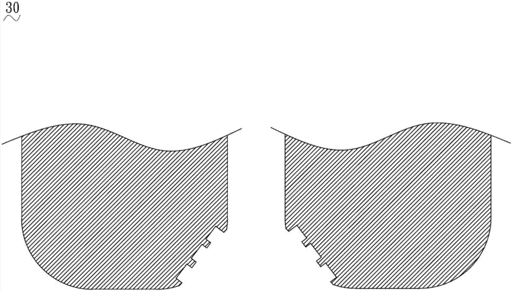
[0058] The above-mentioned welding chopper 430 is prepared by dry pressing, and the dry pressing equipment 50 is as follows: Figure 8 Shown, preparation method comprises the following steps:

[0059] Preparatory stage: pass the setting wire 51 sequentially through the clamping mechanism 52, the pressing plate 53, the punch 54, the mold cavity 56 formed by the docking of the left half mold 55a and the right half ...


PUM


Abstract

The invention relates to a welding cleaver which includes a connecting part and a mouth part connected with the connecting part. The welding cleaver has a path in the middle. The path extends from the top of the connecting part to the bottom of the mouth part, and communicates the connecting part and the mouth part. The path includes a cylindrical slot and a conical slot communicated with the cylindrical slot. The diameter of the cylindrical slot is greater than that of the conical slot. According to the free attenuation characteristic of ultrasonic wave, the path which is composed of a cylindrical slot and a conical slot connected together improves the mass proportion of the mouth part, reduces the ultrasonic transmission damping, improves the efficiency of ultrasonic transmission, and reduces energy loss. As the mouth part has no groove for hiding material residue, users do not need to worry about the problem that the service life of the welding cleaver is affected due to metal residual in the welding process. The connecting part and the mouth part are coupled without transition, and therefore, the welding cleaver can be prepared integrally through injection molding and dry-pressing molding, and is easy to produce.

Description

technical field [0001] The invention relates to the technical field of welding tools for wires and semiconductor devices, in particular to a welding chopper and a preparation method thereof. Background technique [0002] There are three common traditional welding rivets, the first such as figure 1 The welding capillary 10 has a cylindrical body portion and a tapered portion, an axial passage extends from the rear end of the capillary to the end, and a lead wire is welded at the end through the axial passage. or as figure 2 The welding capillary 20, the welding capillary is a three-section coupling structure, including a first cylindrical portion with a first diameter, a second cylindrical portion smaller than the first diameter, a tapered portion coupled to the second cylindrical portion, and an axial The passage extends from the tail end of the rivet to the tip, and a lead wire is soldered at the end through the axial passage. or as image 3 The welding cape 30 of the ...

Claims


Application Information

Patent Timeline
Patent Type & Authority Applications(China)
IPC IPC(8): H01L21/607C04B35/622C04B35/10B28B23/04B28B3/26
CPCB28B3/26B28B23/043C04B35/10C04B35/622C04B2235/3244C04B2235/656C04B2235/6562C04B2235/658H01L24/78H01L2224/78304
Inventor 邱基华
Owner CHAOZHOU THREE CIRCLE GRP
Why Eureka
Try Eureka