Broadband planar end-fire circularly-polarized antenna

A circularly polarized antenna, plane technology, applied in the resonant antenna, radiating element structure and other directions, can solve the problems of unfavorable antenna system miniaturization, high profile, complex structure, etc. compact effect

Inactive Publication Date: 2017-10-20
NANJING UNIV OF SCI & TECH
View PDF3 Cites 11 Cited by
  • Summary
  • Abstract
  • Description
  • Claims
  • Application Information

AI Technical Summary

Problems solved by technology

Although this type of circularly polarized antenna can achieve a wide bandwidth, its comple

Method used


Image

  • Broadband planar end-fire circularly-polarized antenna
  • Broadband planar end-fire circularly-polarized antenna
  • Broadband planar end-fire circularly-polarized antenna

Examples


Embodiment 1

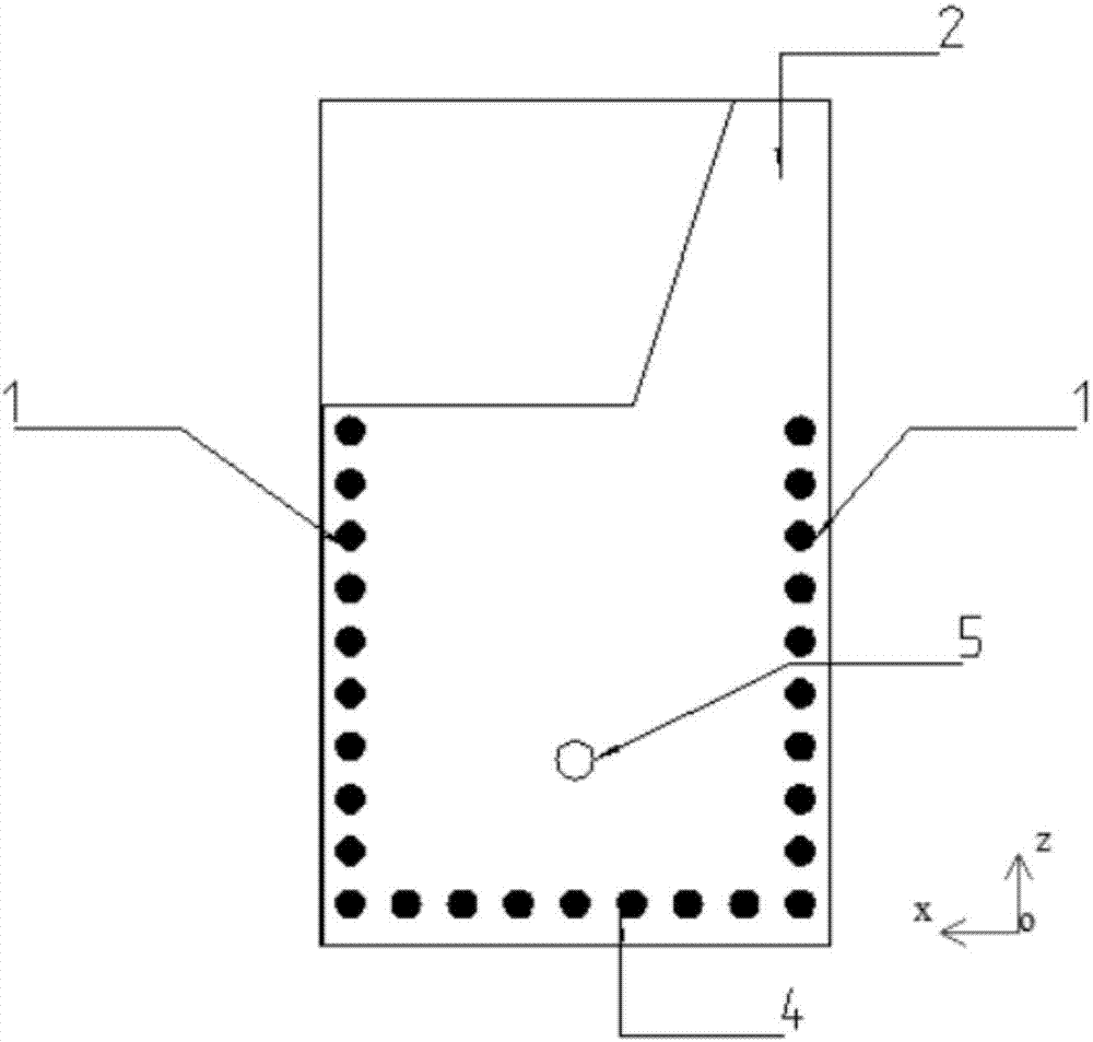
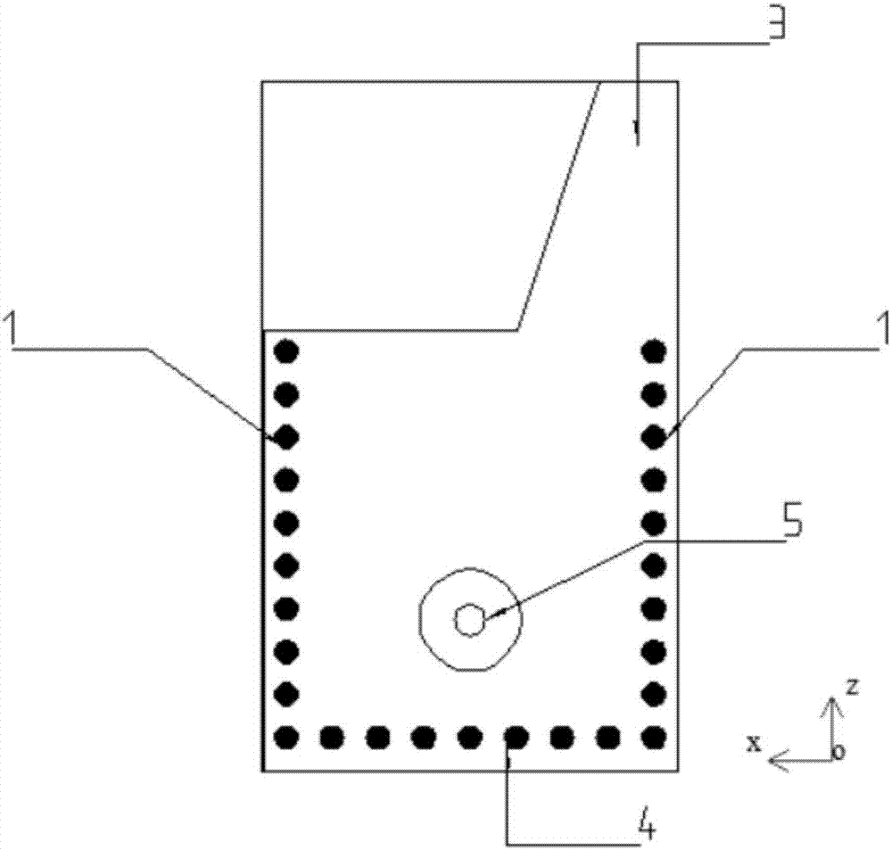
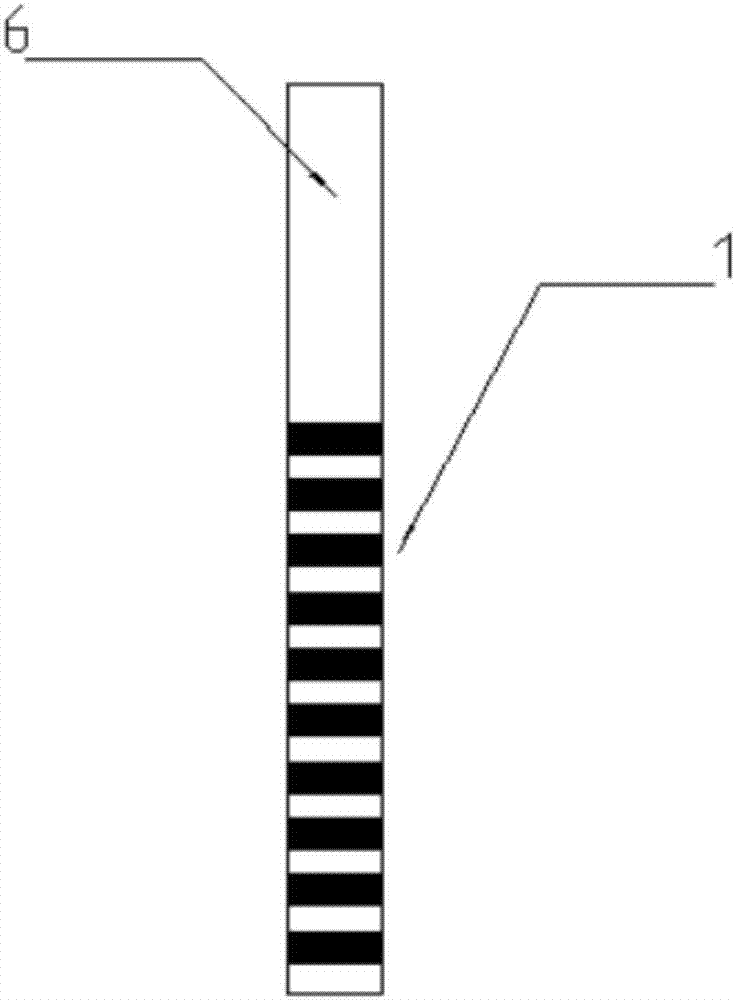
[0028] A broadband planar end-fired circularly polarized antenna, with a single-layer dielectric plate structure, including a dielectric substrate 6, the upper surface of the dielectric substrate is coated with a layer of metal 2, the front end of the metal layer is a linear gradient structure, and the lower layer of the dielectric substrate is coated with a layer of metal 3. The front end of the metal layer is a linear gradient structure, which is symmetrical to the gradient structure of the upper layer. There are three rows of metallized through holes on the dielectric substrate: two rows of metallized through holes 1 on the left and right and one row of metallized through holes 4 at the bottom of the antenna. There is a feed point 5 on the dielectric substrate.

[0029] figure 1 A front view of the overall structure of the antenna of the present invention is given, figure 2 A rear view of the overall structure of the antenna of the present invention is given, image 3 Gi...


PUM

PropertyMeasurementUnit
Widthaaaaaaaaaa
Lengthaaaaaaaaaa
Thicknessaaaaaaaaaa

Abstract

The invention discloses a broadband planar end-fire circularly-polarized antenna. The antenna is of a single-layer dielectric plate structure which is divided into an SIW structure and a front-back linear tapered slot structure. The antenna includes a dielectric substrate which is plated with an upper metal layer on the upper surface and a lower metal layer on the lower surface. The SIW structure has three rows of plated through holes, namely, left and right rows of plated through holes symmetric about the central axis of the dielectric substrate and a row of plated through holes at the bottom of the antenna. The dielectric substrate is provided with a feed point. The upper metal layer and the lower metal layer of the front-back linear tapered slot structure are of a right trapezoid structure, and the upper bases of the right trapezoids coincide with the top end of the single-layer dielectric plate. The broadband planar end-fire circularly-polarized antenna adopts a substrate integrated waveguide, and has the advantages of simple structure, circular polarization, wide band, low cost, low profile, and easiness to be conformal.

Description

technical field [0001] The invention relates to the field of circularly polarized antennas, in particular to a planar broadband end-fired circularly polarized antenna. Background technique [0002] Circularly polarized antennas are widely used in satellite communications, radar detection, etc. Although the common horn circularly polarized antenna has a wider bandwidth, it has a higher profile. In order to reduce the profile and volume, a common method is to use a microstrip antenna to achieve circular polarization. Although the volume is reduced, the bandwidth is limited, and the radiation direction can only be the side beam direction, which does not meet the needs of many occasions. Therefore, it is of potential application value to design a wide-band, low-profile circularly polarized antenna with end-fired radiation direction. [0003] Existing planar end-fire circularly polarized antennas are mostly realized by using a magnetic microstrip dipole and a pair of laterally ...

Claims


Application Information

Patent Timeline
IPC IPC(8): H01Q1/38H01Q9/04
Inventor 张金栋陈祥云吴翠翠陈峤羽吴文冯敏姚祺汤普祥周雅莉张弘毅韦一方陈国杭汪映展李光
Owner NANJING UNIV OF SCI & TECH
Why Eureka
Try Eureka