
Permanent magnet speed regulator

A permanent magnet governor and permanent magnet technology, applied in the field of mechanical transmission, can solve the problems of low unit magnetic flux density and large governor volume, and achieve the effects of increased service life, high volume power density and load reduction

Pending Publication Date: 2017-10-20
诸暨和创电机科技有限公司
View PDF6 Cites 3 Cited by
  • Summary
  • Abstract
  • Description
  • Claims
  • Application Information

AI Technical Summary

Problems solved by technology

Due to the ferromagnetism of the iron core, the permanent magnet rotor can only provide a magnetic field to the rotor winding from one direction, and the unit magnetic flux density is low. In order to ensure the transmission efficiency, the volume of the governor has to be large enough to carry enough The permanent magnet rotor and winding

Method used


Image

  • Permanent magnet speed regulator
  • Permanent magnet speed regulator
  • Permanent magnet speed regulator

Examples


Embodiment Construction

[0029] Below in conjunction with each accompanying drawing, the present invention is described in detail.

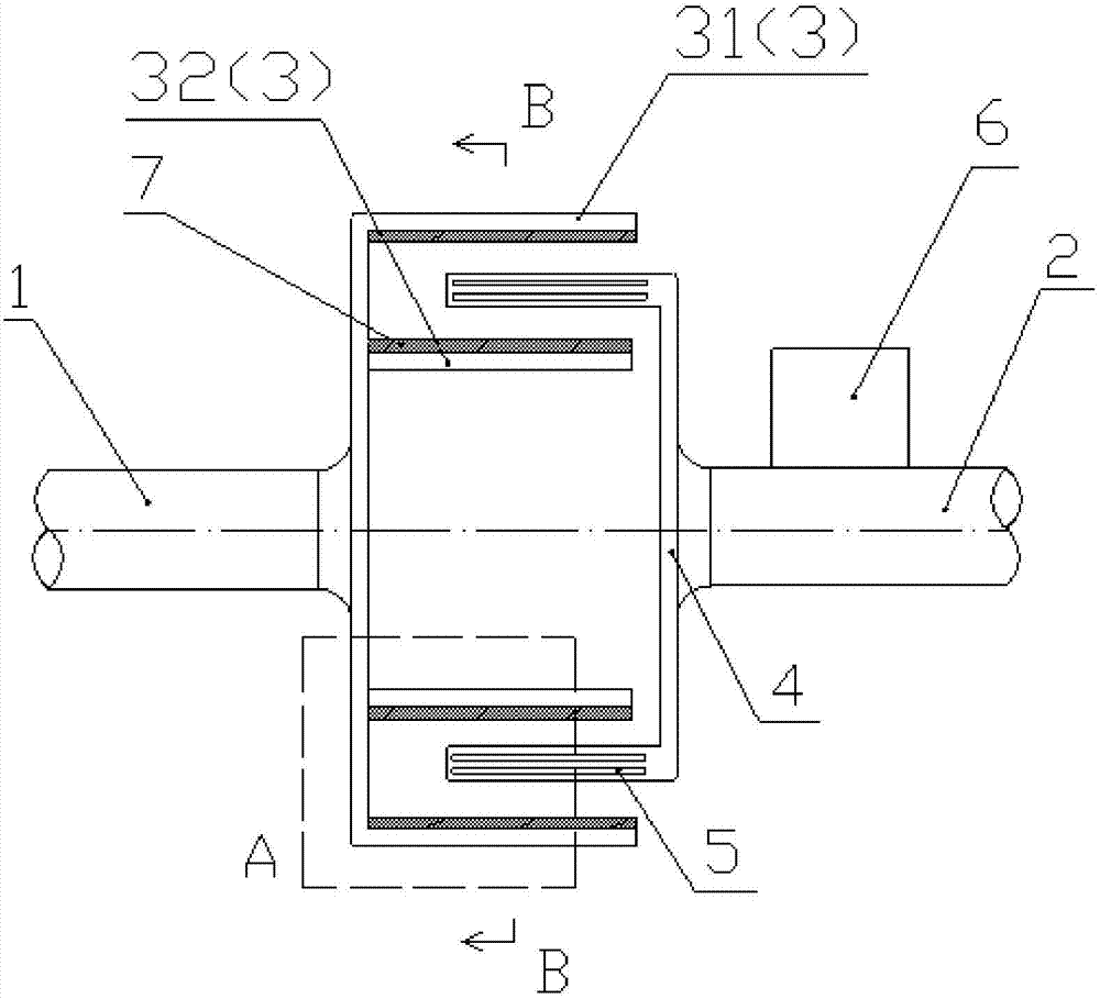
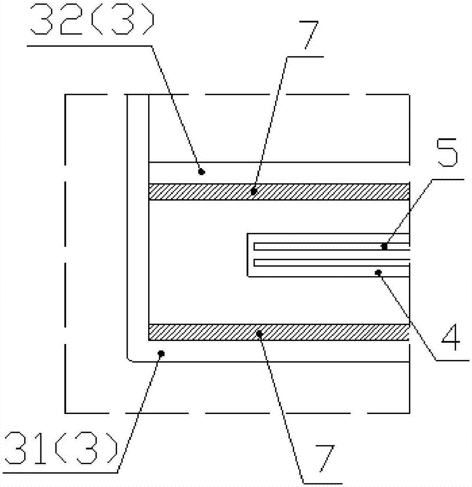
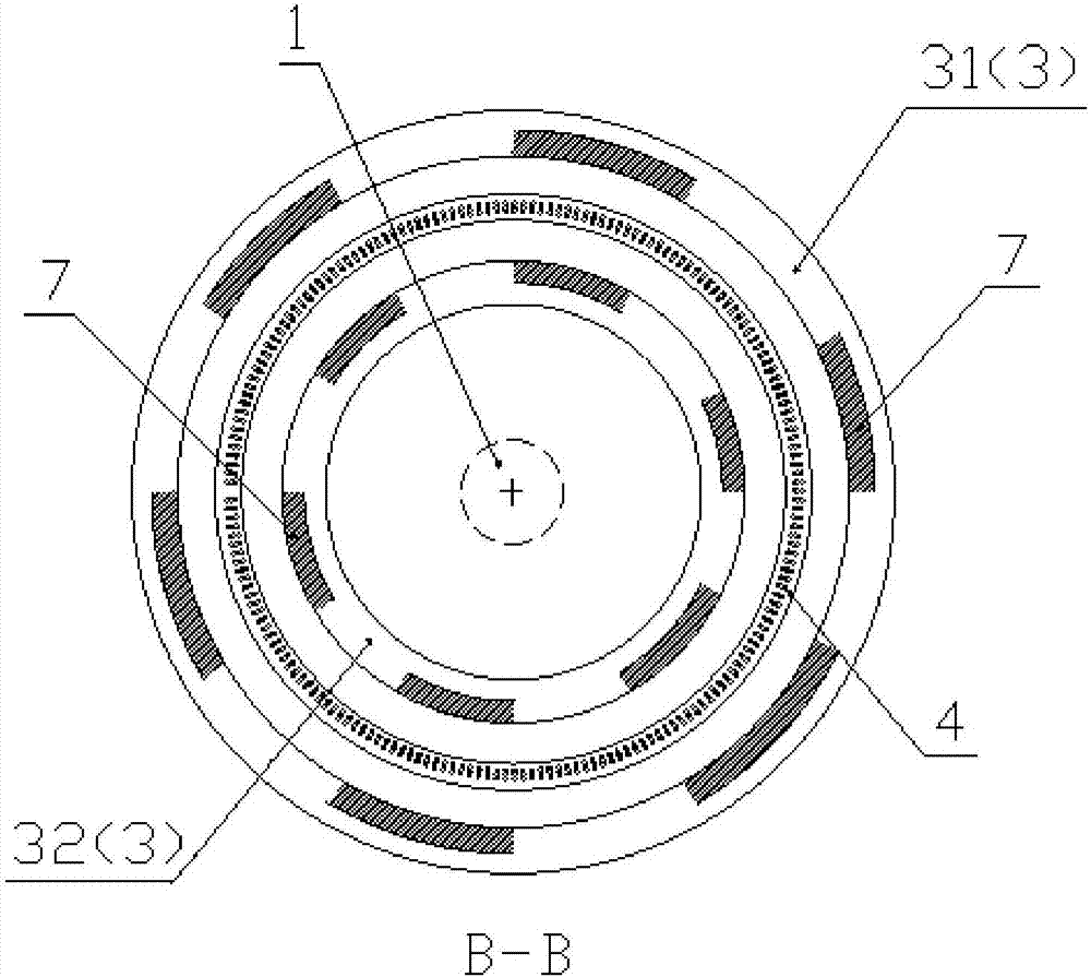
[0030] Please refer to figure 1 and figure 2 , the embodiment of the present invention provides a permanent magnet governor, including: a driving shaft 1, a driven shaft 2, a permanent magnet rotor set 3, a rotor winding 5, a speed regulating device 6 and a polymer plastic carrier 4; the permanent magnet rotor set 3 is connected to the driving shaft 1, and the polymer plastic carrier 4 is connected to the driven shaft 2; the axes of the driving shaft 1 and the driven shaft 2 coincide; the permanent magnet rotor group 3 is provided with a permanent magnet rotor 7 for driving A changing magnetic field is generated when the shaft 1 rotates; the rotor winding 5 is arranged on the polymer plastic carrier 4 , and the rotor winding 5 is connected to the speed regulating device 6 for adjusting the rotational speed of the driven shaft 2 .

[0031] The driving shaft 1 drives th...


PUM


Abstract

The invention discloses a permanent magnet speed regulator comprising a driving shaft, a driven shaft, permanent magnet rotor sets, rotor windings, a speed regulating device and a high molecular plastic carrier. The permanent magnet rotor sets are connected with the driving shaft in a transmission way. The high molecular plastic carrier is connected with the driven shaft in a transmission way. The axes of the driving shaft and the driven shaft are overlapped. The permanent magnet rotor sets are provided with permanent magnet rotors and used for generating a varying magnetic field in rotation of the driving shaft. The rotor windings are arranged on the high molecular plastic carrier. The rotor windings are connected with the speed regulating device and used for regulating the rotating speed of the driven shaft. The high molecular plastic carrier is manufactured by high molecular plastics so that the supporting structure can be optimized, the rotational inertia can be reduced, the servo-actuating performance of the rotor windings can be enhanced and regulation is enabled to be more rapid and accurate; and the wear rate between the rotor windings and the carbon brush can be reduced so that the service life can be enhanced.

Description

technical field [0001] The invention relates to the field of mechanical transmission, in particular to a permanent magnet governor. Background technique [0002] Permanent magnet speed control technology is a breakthrough new technology developed internationally in recent years, and it is an applicable technology for speed control and energy saving of centrifugal loads such as fans and pumps. It has the characteristics of high efficiency and energy saving, high reliability, no rigid connection to transmit torque, can be applied in harsh environments, greatly reduces the overall system vibration, reduces system maintenance and prolongs the service life of the system, making it an energy-saving technology for fans and pumps. Top choice for remodeling. [0003] The problem is that the rotor windings of the existing permanent magnet governors are all attached to the supporting structure of the iron core, whether they are of the drum type or the disk type. Due to the ferromagne...

Claims


Application Information

Patent Timeline
Patent Type & Authority Applications(China)
IPC IPC(8): H02K49/10
CPCH02K49/108
Inventor 李和良吴伟明
Owner 诸暨和创电机科技有限公司
Learn More