Inverter control unit and air conditioner

A control device and inverter technology, applied in refrigerators, control systems, vector control systems, etc., can solve problems such as the inability to reduce the cost of microcomputers with AD conversion units, and achieve the effect of cost reduction

Active Publication Date: 2019-08-09
HITACHI JOHNSON CONTROLS AIR CONDITIONING INC
View PDF11 Cites 0 Cited by
  • Summary
  • Abstract
  • Description
  • Claims
  • Application Information

AI Technical Summary

Problems solved by technology

[0004] However, in the technology described in Patent Document 1, when the position sensorless control is performed on a plurality of DC motors, AD conversion units (two AD conversion units or one high-speed AD conversion unit) are required for the number of DC motors, so there is a problem that cannot be achieved. The issue of cost reduction of microcomputers equipped with AD conversion units

Method used


Image

  • Inverter control unit and air conditioner
  • Inverter control unit and air conditioner
  • Inverter control unit and air conditioner

Examples


no. 1 approach

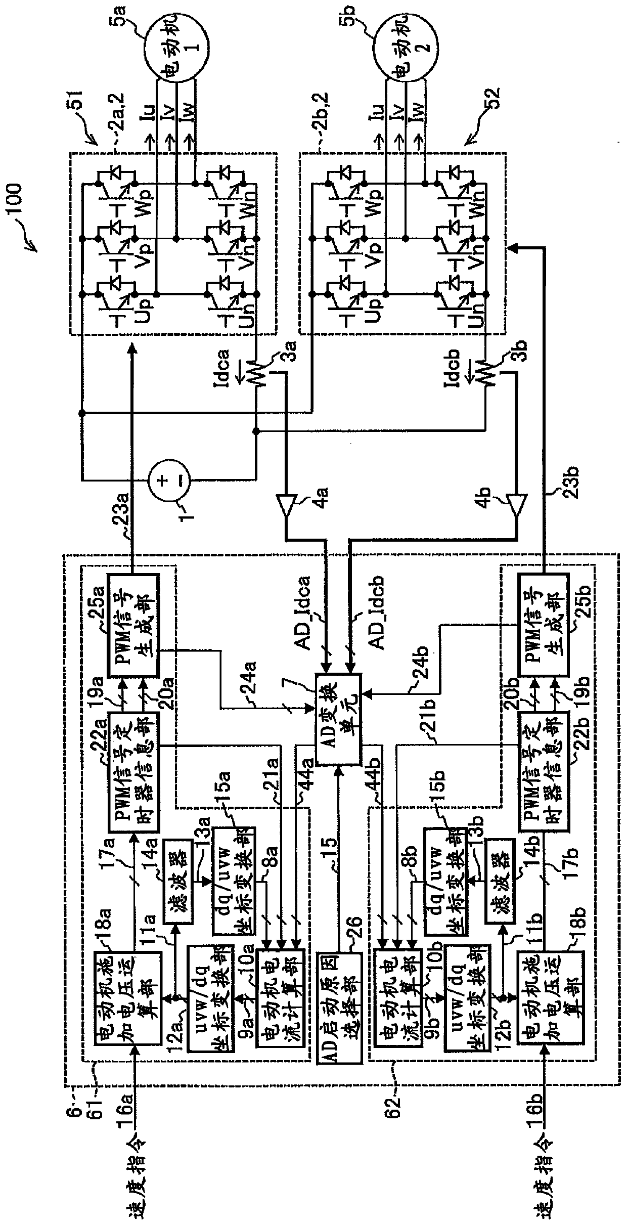
[0067] figure 1 It is a block diagram showing the inverter control device according to the first embodiment of the present invention. In each figure, the same reference numerals are assigned to common constituent elements, and overlapping descriptions are omitted.

[0068] Such as figure 1 As shown, the inverter control device 100 includes: a DC power supply 1 that supplies DC power, a first inverter unit 51, a second inverter unit 52, and a brushless DC motor (first motor) 5a that can be individually controlled. and the controller 6 (inverter control unit) of the brushless DC motor (second motor) 5b.

[0069]

[0070]The first inverter unit 51 (first inverter circuit) includes: a first inverter circuit 2a for converting DC power from the DC power supply 1 into AC power; The shunt resistor 3a, the voltage amplifying circuit 4a for amplifying the voltage across the shunt resistor 3a, and the brushless DC motor 5a connected to the first inverter circuit 2a.

[0071] The se...

no. 2 approach

[0135] The second embodiment is an example in which the calculation timing of the inverter control is further subtracted.

[0136] Figure 6 The first and second carrier signals, the AD conversion start triggers 24a and 24b, and the calculations of the first inverter control unit 61 and the second inverter control unit 62 of the inverter control device according to the second embodiment of the present invention are shown. timing.

[0137] The structure of the inverter control device of the second embodiment and figure 1 The inverter control device 100 is the same. AD activation reason selection part 26 (refer to figure 1 ) is set to perform AD conversion and inverter calculation of the detection current by taking in the AD converter start trigger 24a, 24b once in four cycles of the PWM carrier (for updating the motor applied voltage information based on the current calculation value ). Also, a selection is made to divide the first inverter calculation by the first inverte...

no. 3 approach

[0141] Regarding the calculation timing of the inverter control, the third embodiment is an example in which the calculation is performed every PWM carrier period.

[0142] Figure 7 The first and second carrier signals, AD conversion start triggers 24a and 24b, and calculations of the first inverter control unit 61 and the second inverter control unit 62 of the inverter control device according to the third embodiment of the present invention are shown. timing.

[0143] The structure of the inverter control device of the third embodiment and figure 1 The inverter control device 100 is the same.

[0144] Such as Figure 7 As shown, the first inverter control unit 61 performs AD conversion when the first carrier signal is counting up, and performs inverter calculation when the first carrier signal is counting down. exist Figure 7 In the example of , the first inverter control unit 61 performs AD conversion when the timing T0 to T1 (T0' to T1') of the carrier half cycle of...


PUM


Abstract

A controller of an inverter control apparatus includes an A / D conversion unit that performs digital conversion of an input signal when a signal for either an A / D converter start trigger or an A / D converter start trigger is input thereinto; a first inverter control unit that generates the A / D converter start trigger which starts the A / D conversion unit, based on A / D converter start timing information and a first carrier signal; a second inverter control unit that generates the A / D converter start trigger which starts the A / D conversion unit, based on A / D converter start timing information and a second carrier signal; and an A / D start factor selection unit that receives either the A / D converter start trigger or the A / D converter start trigger and selects an A / D start factor at a predetermined period timing of an operation period of the first carrier signal and the second carrier signal.

Description

technical field [0001] The invention relates to an inverter control device and an air conditioner. Background technique [0002] In refrigeration devices such as air conditioners and refrigerators, inverter control devices for driving high-efficiency motors such as brushless DC (Direct Current) motors are widely used from the viewpoint of reducing power consumption. As a method of driving the motor, there is a more efficient sine wave drive method that can reduce noise than a square wave current drive method with a simple control structure. In the case of the sine wave drive method, the inverter control device controls the motor at an arbitrary rotational speed based on vector control theory that determines the phase and magnitude of the output voltage using position information of the motor rotor magnetic poles. As a means of detecting position information of a motor rotor magnetic pole, there is a position sensorless control technique in which a motor current flowing in e...

Claims


Application Information

Patent Timeline
Patent Type & Authority Patents(China)
IPC IPC(8): H02P27/08
CPCH02P27/085F25B13/00F25B49/025F25B2313/0293F25B2313/0294F25B2600/021H02P6/04H02P6/18H02P21/24H02P27/08Y02B30/70
Inventor 笠原励李东升
Owner HITACHI JOHNSON CONTROLS AIR CONDITIONING INC
Why Eureka
Try Eureka