Forming method of silica gel diaphragm, silica gel diaphragm and sounding device

A technology of silicone diaphragm and molding method, which is applied to sensors, electrical components, loudspeakers, etc., can solve the problems of reducing product reliability, deformation of polymer diaphragms, and difficulty in bonding other components, and achieves the effect of suppressing rolling vibration. , Improve the overall strength, increase the effect of damping characteristics

Active Publication Date: 2020-12-04
SSI NEW MATERIAL (ZHENJIANG) CO LTD
View PDF5 Cites 0 Cited by
  • Summary
  • Abstract
  • Description
  • Claims
  • Application Information

AI Technical Summary

Problems solved by technology

During injection molding, liquid silicone is injected into the mold cavity by pressure to wrap the polymer membrane inside the mold cavity. Due to the impact of pressure and liquid flow, the polymer membrane will be impacted, resulting in deformation or position change of the polymer membrane. , which affects the quality of the molded silicone diaphragm
[0003] In addition, in the existing silicone diaphragm, the polymer diaphragm is only located at the ring portion of the silica gel diaphragm. The shape of the polymer diaphragm is not complete, and the polymer diaphragm is more likely to be deformed during the process.
[0004] Furthermore, the exposed surface of the existing silica gel diaphragm is silica gel. Due to the characteristics of silica gel, it is not easy to bond with other components, causing other components to fall off easily, reducing product reliability.

Method used


Image

  • Forming method of silica gel diaphragm, silica gel diaphragm and sounding device
  • Forming method of silica gel diaphragm, silica gel diaphragm and sounding device
  • Forming method of silica gel diaphragm, silica gel diaphragm and sounding device

Examples


Embodiment approach 1

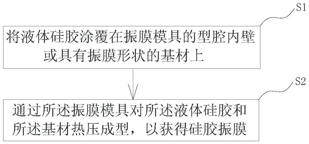
[0059] like Figure 1 to Figure 12 As shown, the invention provides a molding method of a silica gel diaphragm, which comprises the following steps:

[0060] Step S1: coating the liquid silicone 1' on the inner wall of the cavity 31 of the diaphragm mold 3 or the substrate 2 having the shape of the diaphragm;

[0061] Step S2: The liquid silicone 1' and the substrate 2 are thermally press-molded through the diaphragm mold 3 to obtain a silica gel diaphragm 10.

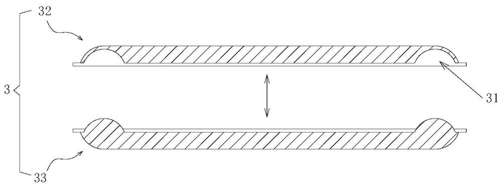
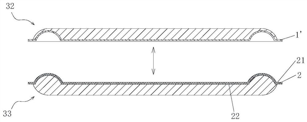
[0062] Specifically, such as figure 2 As shown, the diaphragm mold 3 includes an upper mold 32 and a lower mold 33 that can be buckled together. After the upper mold 32 and the lower mold 33 are buckled, a cavity 31 that can accommodate the substrate 2 and the liquid silicone 1' is formed. In this embodiment, the structure of the cavity 31 is consistent with the structure of the silicone diaphragm 10 to be formed; The structure of the diaphragm 10 is consistent. Please refer to Figure 7 to Figure 12 As shown, th...

Embodiment approach 2

[0076] like Figure 7 to Figure 12 As shown, the present invention also provides a silica gel diaphragm 10, which is made by the molding method of the silica gel diaphragm described in the first embodiment, wherein the molding method of the silica gel diaphragm has been specifically described in the first embodiment , the selected materials, process steps and beneficial effects will not be repeated here. The silicone diaphragm 10 includes a substrate 2 and a silica gel layer 1 positioned on one side of the substrate 2. The silica gel diaphragm 10 has a ring portion 102, and the inner periphery of the ring portion 102 is connected with a center paste portion 101. The outer peripheral edge of the ring portion 102 is connected with a hanging edge portion 103 . Wherein, the ring part 102 is a ring-shaped structure or other curved structure that is raised relative to the surface of the middle post part 101. Concave-convex shape structure is provided on it, and the hanging edge po...

Embodiment approach 3

[0087] like Figure 16 and Figure 17 As shown, the present invention also provides a sounding device 20, which includes a magnet structure 5, a frame 4 and a silicone diaphragm 10, wherein the silica gel diaphragm 10 is the silica gel diaphragm described in Embodiment 2, and its specific structure, The molding process, working principle and effective effect will not be repeated here. The magnet structure 5 has a magnetic bowl 51, a magnet block 52 is bonded inside the magnetic bowl 51, and a magnet top plate 53 is bonded to the magnet block 52; one side of the basin frame 4 is sealed and connected with the magnetic bowl 51; the silicone diaphragm 10 is sealed Connected to the other side of the basin frame 4 , the silicone diaphragm 10 is connected with a voice coil 7 , and the voice coil 7 is located in the magnetic bowl 51 .

[0088] Specifically, the magnet structure 5 mainly establishes a fixed magnetic field for the sound generating device 20 . The magnet structure 5 a...


PUM


Abstract

The invention provides a forming method for a silica gel vibrating diaphragm, the silica gel vibrating diaphragm and a sounding device. The forming method for the silica gel vibrating diaphragm comprises the following steps of step S1.coating liquid silicone rubber on the inner wall of a cavity of a vibrating diaphragm mold or a substrate with a vibrating diaphragm shape; and step S2.carrying out hot press molding on the liquid silicone rubber and the substrate through the vibrating diaphragm mold in order to obtain the silica gel vibrating diaphragm. According to the forming method for the silica gel vibrating diaphragm, the silica gel vibrating diaphragm and the sounding device, the silica gel vibrating diaphragm is obtained by carrying out hot press molding on the liquid silicone rubber and the substrate, so that the deformation or position change of the substrate is avoided, the risk of easiness in falling off after the silica gel and other components are stuck is avoided, the torsional rigidity and the damping are increased, and the amplitude and the rolling vibration amplitude are reduced.

Description

technical field [0001] The invention relates to the technical field of electronic products, in particular to a method for forming a silica gel diaphragm, a silica gel diaphragm and a sounding device. Background technique [0002] The existing silica gel diaphragm is composed of a silica gel layer and a polymer diaphragm embedded in the silica gel layer, and the silica gel diaphragm is obtained by injection molding. During injection molding, liquid silicone is injected into the mold cavity by pressure to wrap the polymer membrane inside the mold cavity. Due to the impact of pressure and liquid flow, the polymer membrane will be impacted, resulting in deformation or position change of the polymer membrane. , and affect the quality of the formed silicone diaphragm. [0003] In addition, in the existing silicone diaphragm, the polymer diaphragm is only located at the ring portion of the silica gel diaphragm, the shape of the polymer diaphragm is not complete, and the polymer di...

Claims


Application Information

Patent Timeline
Patent Type & Authority Patents(China)
IPC IPC(8): H04R9/06H04R9/02
CPCH04R9/02H04R9/06H04R2400/11
Inventor 金明昱杜娜
Owner SSI NEW MATERIAL (ZHENJIANG) CO LTD
Why Eureka
Try Eureka