
Ceramic plate preventing scalding and making method

A plate and ceramic technology, applied in the field of kitchen plates, can solve the problems of not being able to fully touch the hands without being hot, complicated operation, large handle volume ratio and hot melt, etc.

Inactive Publication Date: 2017-10-24
ZHUJI ZHILIAN ELECTRONICS TECH CO LTD
View PDF3 Cites 0 Cited by
  • Summary
  • Abstract
  • Description
  • Claims
  • Application Information

AI Technical Summary

Problems solved by technology

[0002] The dishes used in the kitchen often need to be steamed. When the cooking is finished, it is difficult to take it out from the cooking environment because the whole plate is high temperature. The current methods have certain shortcomings.
[0003] Usually, after cooking, you need to use clips or brackets to take the plate out from the high temperature environment. This kind of operation is more complicated and requires certain skills.
[0004] The method without clips is to use a heat-insulating low-temperature medium to isolate the high-temperature plate, and then touch the insulating medium with your hands to take the plate out of the cooking environment. This method cannot completely prevent the hands from being hot, and the operation is more cumbersome
[0005] There is a double-layer plate on the market, the middle of the two layers is vacuum or air-filled, but this kind of plate may be suitable for holding high-temperature things. If it is used to steam and cook food, due to the relatively large thermal resistance, the heat is not easily transferred from the outside to the inside of the plate.
[0006] Some of the existing dishes also have handles. The volume ratio of the handles on the market is relatively large compared to the heat fusion, which cannot fully achieve the purpose of not being hot when touched after high-temperature cooking.

Method used


Image

  • Ceramic plate preventing scalding and making method

Examples


Embodiment approach 1

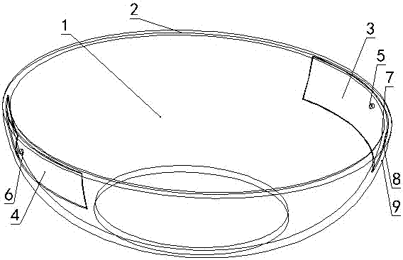
[0014] Embodiment 1 of the present invention: as figure 1 Shown: a non-hot ceramic plate, which includes a plate body 1 and two hollow structures 3, 4, the two same hollow structures 3, 4 are symmetrically arranged relative to the plate body 1, and the hollow structures 3, 4 are separated from the opening of the plate body The distance between the edge 2 is 2cm, the shape of the plate body 1 is a rotating body, the shape of a vegetable plate, and the hollow structure 3 includes a three-layer structure, the inner ceramic layer 7, the middle air layer 8 and the outer ceramic layer, the thickness of the inner and outer ceramics is 1mm, and the entire plate It is composed of two materials with different thermal conductivity. The ceramic material of the hollow structure 3 and 4 has a thermal conductivity not greater than 1w / (m·k). The purpose is to increase thermal resistance and prevent heat from being transferred from the plate to the hand. The plate body 1 The thermal conductiv...


PUM

PropertyMeasurementUnit
Thicknessaaaaaaaaaa
Thermal conductivityaaaaaaaaaa

Abstract

The invention discloses a ceramic plate preventing scalding and a making method. The ceramic plate comprises a plate body, a local hollow structure above the plate, the plate body is composed of ceramic good in heat conductivity coefficient, the hollow structure is composed of ceramic poor in heat conductivity coefficient, the hollow structure comprises three layers which are the inner side ceramic layer, the middle air filling layer and the outer side ceramic layer, the inner side ceramic layer and the outer side ceramic layer are connected with the plate body separately, and the middle air filling layer is closed. The making method comprises the steps of mold making, slip casting, drying, finishing, tapping, painting, glazing and high-temperature calcination. According to the plate, the materials of the air layer, the inner side ceramic layer and the outer side ceramic layer are low in heat conductivity coefficient and large in thermal resistance, the internal and external ceramic of the hollow structure is small in thickness and low in hot melting, and the purpose of taking the plate out of a cooking environment by making the hand make contact with the internal and external ceramic of the hollow structure without scalding the hand can be achieved.

Description

technical field [0001] The invention relates to a non-hot ceramic plate and a production method, which are suitable for the field of kitchen plates. Background technique [0002] The dishes used in the kitchen often need to be steamed. When the cooking is finished, it is difficult to take the plate out from the cooking environment because the whole plate is at high temperature. The current methods have certain shortcomings. [0003] Usually, when the cooking is finished, the plate needs to be taken out from the high temperature environment with the help of clips or brackets. Such an operation is more complicated and requires certain skills. [0004] The method without using clips is to use a heat-insulating low-temperature medium to isolate the high-temperature plate, and then touch the insulating medium with your hands to take the plate out of the cooking environment. This method cannot completely prevent the hands from being hot, and the operation is more cumbersome. [0...

Claims


Application Information

Patent Timeline
IPC IPC(8): A47G19/02
CPCA47G19/02
Inventor 金晓行
Owner ZHUJI ZHILIAN ELECTRONICS TECH CO LTD
Learn More