
A method of using a perforating U-turn device

A technology of equipment and heading machine, which is applied in the field of punching and turning equipment, and achieves the effects of strong practicability, low production cost and simple structure design.

Active Publication Date: 2020-07-03
NINGBO YONGXIN STEEL TUBE
View PDF9 Cites 0 Cited by
  • Summary
  • Abstract
  • Description
  • Claims
  • Application Information

AI Technical Summary

Problems solved by technology

Steel pipe processing is a commonly used product in the industry, but in the further processing of such products as drilling, because the length of steel pipe production is longer, how to make further adjustments to reduce labor costs

Method used


Image

  • A method of using a perforating U-turn device
  • A method of using a perforating U-turn device
  • A method of using a perforating U-turn device

Examples


Embodiment Construction

[0028] The present invention will be further described below in conjunction with the accompanying drawings and specific embodiments.

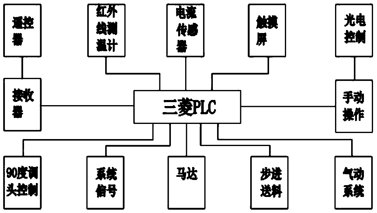
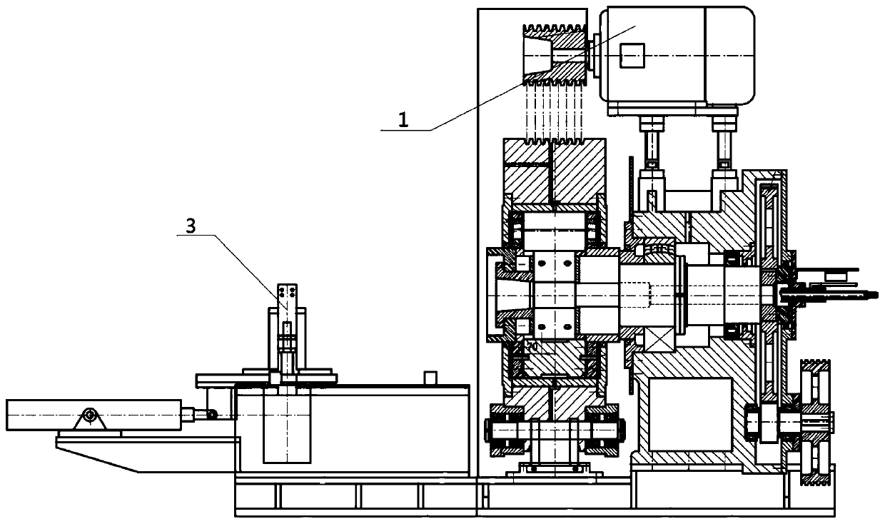
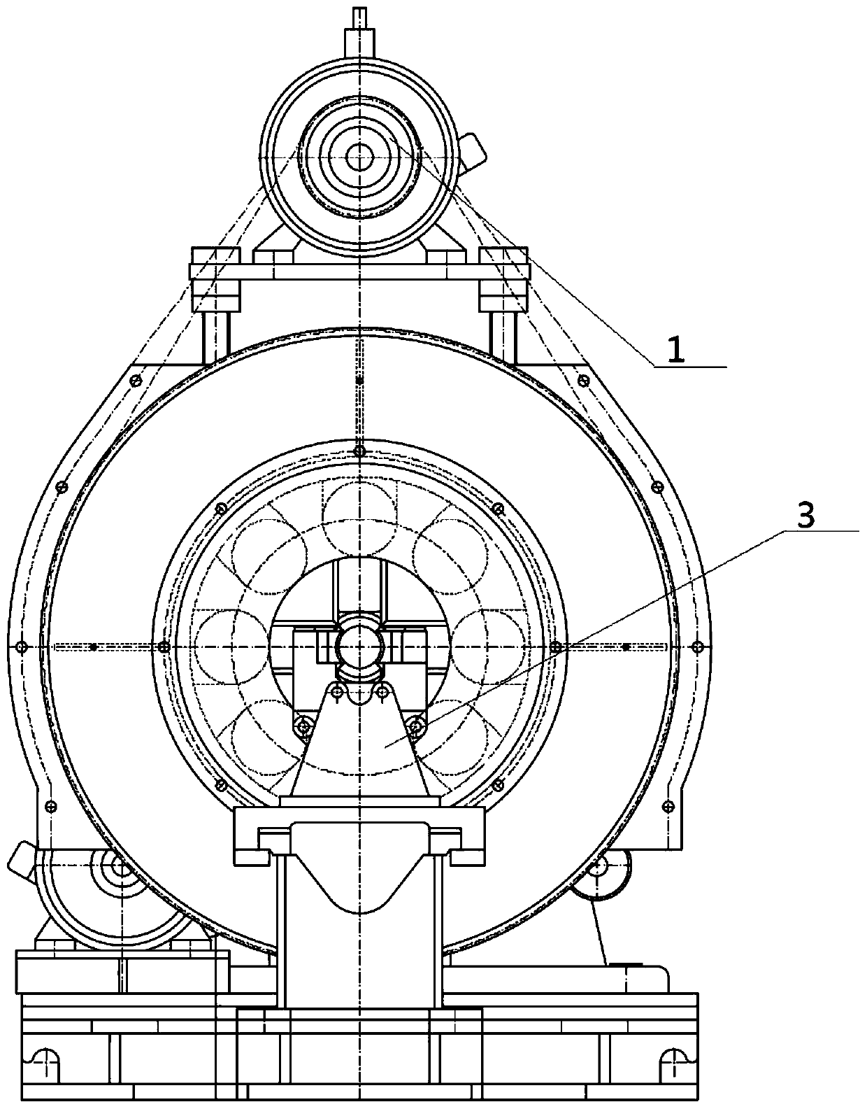
[0029] Such as Figure 1 to Figure 5 As shown, a method of using a piercing and turning equipment, the equipment mainly includes a PLC module, a signal monitoring module, a photoelectric switch, a cooling mechanism, a heading machine, a roll box, a gantry and a rod piercing trolley. The device is also equipped with a remote controller, a receiver and a touch screen, so as to achieve remote control of the machine and the touch screen for control, specifically including the following steps:

[0030] 101) Material heating treatment step: controlled by the PLC module of the equipment, the steel pipe material is sent into the walking furnace, and the walking furnace is continuously heated to a high temperature, and the high temperature is 1000°C to 1300°C. The walking furnace is a device with fixed height, width and length. The PLC module adopts M...


PUM


Abstract

The invention discloses a use method of a punching turning-around device. The method specifically comprises following steps of material heating treatment, conveying separating, roller shaping, steep pipe conveying, heading treatment and cooling transmission. The use method of the punching turning-around device saves cost and facilitates manufacturing.

Description

technical field [0001] The present invention relates to processing equipment, more specifically, it relates to a method of using perforating and turning equipment. Background technique [0002] With the rapid development of modern science and technology, the fully automated production of various industries has been greatly improved, and the production efficiency has been greatly improved. Steel pipe processing is a commonly used product in the industry, but in the further processing of such products as drilling, because the length of steel pipe production is longer, how to further adjust to reduce labor costs. It has become a problem that many companies consider. Contents of the invention [0003] The invention overcomes the deficiencies of the prior art and provides a method for using a punching and turning device that is cost-saving and convenient to manufacture. [0004] Technical scheme of the present invention is as follows: [0005] A method for using a perforatin...

Claims


Application Information

Patent Timeline
Patent Type & Authority Patents(China)
IPC IPC(8): B23P15/00
CPCB23P15/00
Inventor 王兴利庞诗海周玲彭代聪
Owner NINGBO YONGXIN STEEL TUBE
Learn More