Automatic wood cutting and grooving machine

A slotting machine and wood technology, applied in the direction of slotting machines, mortising machines, wood processing equipment, etc., can solve the problems of inconvenient operation, increased time cost, high cost, etc., to shorten production time, reduce workload, The effect of easy operation

Inactive Publication Date: 2017-10-24
湖州南浔亨力木制品厂
View PDF5 Cites 6 Cited by
  • Summary
  • Abstract
  • Description
  • Claims
  • Application Information

AI Technical Summary

Problems solved by technology

[0002] At present, wooden doors on the market need to be spliced ​​from multiple boards. The boards are cut from a piece of round wood. When the round wood is cut, when a piece of wood is cut to form a board, the worker needs to take down the board, and then each piece Take it away and form a semi-finished wood board, which is inconvenient to operate, and requires multiple handling and movements during the processing process, which increases time cost and low efficiency; the semi-finished wood board needs to be grooved on the side so that the two wood boards can be spliced ​​and bonded together. When slotting and the convex edge of the wood board can fit together, the splicing is more firm, but when the existing semi-finished wood board is slotting, the slots opened are relatively simple, and the diameter of the slot is determined by the diameter of the slotting milling cutter, but different Plates with different thicknesses need to be slotted with different sizes, and the depths of the slots are also different. To open slots with different sizes, it is necessary to replace the slotting milling cutters of different specifications, and the cost is high.
Therefore, the existing wood has the problems of inconvenient operation, low efficiency and high cost when cutting and grooving

Method used


Image

  • Automatic wood cutting and grooving machine
  • Automatic wood cutting and grooving machine
  • Automatic wood cutting and grooving machine

Examples


Embodiment Construction

[0020] The present invention will be further described below in conjunction with the accompanying drawings and embodiments, but not as a basis for limiting the present invention.

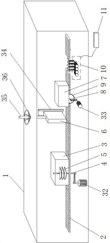
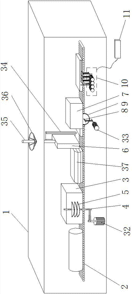
[0021] Example. An automatic wood cutting and slotting machine, constituted as Figures 1 to 7 As shown, including frame 1, frame 1 is provided with conveying device 2, and one end of conveying device 2 is provided with cutting box 3; A baffle plate 6 is provided, and one end of the baffle plate 6 is provided with a side trimming box 7; the bottom end of the side trimming box 7 is provided with a horizontal shaft 8, and a vertical knife saw 9 is installed at both ends of the horizontal shaft 8; one end of the side trimming box 7 is provided with a The slotting device 10 is connected with a knob plate 11 , and the knob plate 11 is arranged outside the frame 1 .

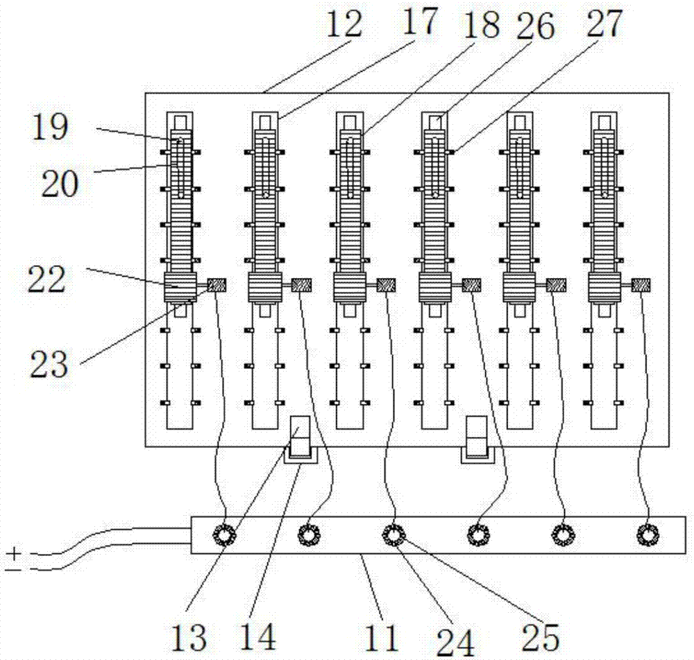
[0022] Described slotting device 10 comprises support 12, and support 12 bottom end is connected with clamp block 13, and clamp block 13 ...


PUM


Abstract

The invention discloses an automatic wood cutting and grooving machine. The automatic wood cutting and grooving machine comprises a machine frame (1); a conveying device (2) is arranged in the machine frame (1); a cutting box (3) is arranged at one end of the conveying device (2); a vertical shaft (4) is arranged outside the cutting box (3); transverse knife saws (5) are arranged on the vertical shaft (4); a baffle (6) is arranged at one end of the cutting box (3); an edge cutting box (7) is arranged at one end of the baffle (6); a transverse shaft (8) is arranged at the bottom end of the edge cutting box (7); vertical knife saws (9) are arranged at the two ends of the transverse shaft (8) separately; a grooving device (10) is arranged at one end of the edge cutting box (7) and is connected with a rotary knob plate (11); and the rotary knob plate (11) is arranged outside the machine frame (1). The automatic wood cutting and grooving machine has the advantages that the efficiency can be improved, the operation performance can be improved, the cost can be lowered, in addition, the structural stability is good, the conveying efficiency is high, the application range is wide, and the precision is high.

Description

technical field [0001] The invention relates to a wood cutting and slotting machine, in particular to an automatic wood cutting and slotting machine. Background technique [0002] At present, wooden doors on the market need to be spliced ​​from multiple boards. The boards are cut from a piece of round wood, and when the round wood is cut, when a piece of wood is cut to form a board, the worker needs to take the board down, and then each piece Take it away and form a semi-finished wood board, which is inconvenient to operate, and many times of handling and movement are required during the processing, which increases the time cost and low efficiency; the semi-finished wood board needs to be grooved on the side so that the two boards can be spliced ​​and bonded together. When slotting and the convex edge of the wood board can fit together, the splicing is more firm, but when the existing semi-finished wood board is slotting, the slots opened are relatively simple, and the diame...

Claims


Application Information

Patent Timeline
Patent Type & Authority Applications(China)
IPC IPC(8): B27C9/00B27F5/02
CPCB27C9/00B27F5/02
Inventor 徐启旺
Owner 湖州南浔亨力木制品厂
Why Eureka
Try Eureka