Automatic rod delivery mechanism of cracking furnace

A pyrolysis furnace, automatic technology, applied in the direction of conveyors, conveyor objects, transportation and packaging, etc., can solve the problems of low loading and unloading rod efficiency, reduce the waste processing efficiency of the waste pyrolysis furnace, and high labor intensity, so as to improve the waste processing efficiency. , the effect of reducing labor intensity and high degree of automation

Inactive Publication Date: 2017-10-24
HENAN DIZHILV ENVIRONMENTAL PROTECTION TECH CO LTD
View PDF0 Cites 0 Cited by
  • Summary
  • Abstract
  • Description
  • Claims
  • Application Information

AI Technical Summary

Problems solved by technology

[0002] With the rapid development of economy and the improvement of urbanization level, garbage cracking treatment has gradually become a new development direction of garbage treatment, which has great advantages, such as: fast and efficient treatment process, less energy consumption, low cost, high resource utilization rate, It is easy to operate and can significantly reduce the harm caused by garbage to the environment, so as to truly realize the harmless treatment of garbage. The outer pressing rod mechanism of the pressing device used in conjunction with the garbage cracking furnace is generally composed of multiple pressing rods, which can be used according to the cracking The height of the furnace requires the number of pressure rods to connect. The connection between the pressure rods is through threaded connections. At present, the loading and unloading of the pressure rods can only be done manually. Every time the pressure rods are loaded and unloaded, people have to climb to Loading and unloading on the top of the furnace is labor-intensive, and the efficiency of the loading and unloading rod is low, which greatly reduces the efficiency of the garbage cracking furnace for processing garbage; Institutions are very necessary

Method used


Image

  • Automatic rod delivery mechanism of cracking furnace
  • Automatic rod delivery mechanism of cracking furnace
  • Automatic rod delivery mechanism of cracking furnace

Examples


Embodiment 1

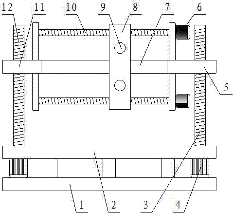
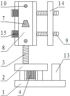
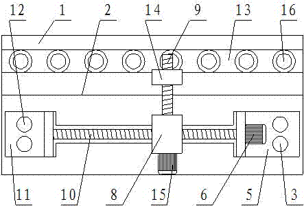
[0017] Such as figure 1 , figure 2 with image 3 Shown, a kind of pyrolysis furnace automatic rod feeding mechanism, it comprises base 1, and the upper surface of described base 1 is provided with motor frame 2, and the positions close to two ends on described motor frame 2 are respectively provided with vertical screw rod A3 and vertical Screw rod B12, described vertical screw rod A3 and the position near the bottom end of vertical screw rod B12 are connected with motor frame 2 in rotation, and the bottom end of described vertical screw rod A3 and vertical screw rod B12 is connected with motor A4, and described vertical screw rod A3 and The position close to the top on the vertical screw rod B12 is respectively threadedly connected with lifting platform A5 and lifting platform B11, and a slideway 7 is fixed between the described lifting platform A5 and the lifting platform B11. Mobile frame 8, described mobile frame 8 is threadedly connected with horizontal screw rod A10, ...

Embodiment 2

[0020] Such as figure 1 , figure 2 with image 3 Shown, a kind of pyrolysis furnace automatic rod feeding mechanism, it comprises base 1, and the upper surface of described base 1 is provided with motor frame 2, and the positions close to two ends on described motor frame 2 are respectively provided with vertical screw rod A3 and vertical Screw rod B12, described vertical screw rod A3 and the position near the bottom end of vertical screw rod B12 are connected with motor frame 2 in rotation, and the bottom end of described vertical screw rod A3 and vertical screw rod B12 is connected with motor A4, and described vertical screw rod A3 and The position close to the top on the vertical screw rod B12 is respectively threadedly connected with lifting platform A5 and lifting platform B11, and a slideway 7 is fixed between the described lifting platform A5 and the lifting platform B11. Mobile frame 8, described mobile frame 8 is threadedly connected with horizontal screw rod A10, ...


PUM


Abstract

The invention relates to an automatic rod-feeding mechanism for a pyrolysis furnace, which comprises a base, a motor frame is arranged on the upper surface of the base, a vertical screw A, a vertical screw B, a vertical screw A and a vertical screw B are respectively arranged on the motor frame near two ends The position close to the top of the top is connected with lifting platform A and lifting platform B through threads respectively, a slideway is fixed between lifting platform A and lifting platform B, and a moving frame is set sliding on the sliding path, and a horizontal screw is connected with a horizontal screw thread on the moving frame A, the horizontal screw A is set parallel to the slideway, the two ends of the horizontal screw A are respectively rotated and set on the upper surface of the lifting platform A and the lifting platform B, and the horizontal screw B perpendicular to the horizontal screw A is arranged on the moving frame, and the horizontal screw The inner end of B is threadedly connected with a manipulator fixing frame, and the bottom of the upper surface of the base is fixed with a rod-changing frame, and the rod-changing frame is provided with fixing grooves arranged in a straight line; in general, the structure design of the present invention is reasonable and automatic High degree.

Description

technical field [0001] The invention belongs to the technical field of garbage treatment, and in particular relates to an automatic rod feeding mechanism for a cracking furnace. Background technique [0002] With the rapid development of economy and the improvement of urbanization level, garbage cracking treatment has gradually become a new development direction of garbage treatment, which has great advantages, such as: fast and efficient treatment process, less energy consumption, low cost, high resource utilization rate, It is easy to operate and can significantly reduce the harm caused by garbage to the environment, so as to truly realize the harmless treatment of garbage. The outer pressing rod mechanism of the pressing device used in conjunction with the garbage cracking furnace is generally composed of multiple pressing rods, which can be used according to the cracking The height of the furnace requires the number of pressure rods to connect. The connection between the...

Claims


Application Information

Patent Timeline
IPC IPC(8): B65G47/90
CPCB65G47/901B65G2201/0217
Inventor 余华龙张振堂何晓锋
Owner HENAN DIZHILV ENVIRONMENTAL PROTECTION TECH CO LTD
Why Eureka
Try Eureka