
A trolley type annealing furnace

An annealing furnace and trolley-type technology, which is applied to furnaces, furnace types, heat treatment furnaces, etc., can solve the problems of uneven temperature of the workpiece, asynchronous heating, slow cooling speed, etc., to save the annealing cycle, reduce production costs, structure simple effect

Active Publication Date: 2018-09-28
CHONGQING JINKAI SPECIAL STEEL PROD
View PDF6 Cites 0 Cited by
  • Summary
  • Abstract
  • Description
  • Claims
  • Application Information

AI Technical Summary

Problems solved by technology

[0003] At present, in the process of heating the workpiece in the current annealing furnace, due to the low thermal efficiency of the radiation heat of the resistance heating in the range of 600-900°C, the energy consumption is high; 50°C slowly shrinks to 5-10°C. In addition, due to the shielding effect of the central workpiece, the heating temperature is lower than the heating temperature near the furnace resistance band, resulting in uneven temperature of the workpiece in the furnace; this large gap will lead to When the two parts are heated asynchronously, the holding time of the workpiece through firing is different, which affects the uniformity of the material structure in the furnace;
[0004] Secondly, according to the requirements of the heat treatment process curve of the current trolley-type annealing furnace, when the furnace temperature reaches less than 702°C and then slowly cools down, the cooling speed is too slow, and the production of special Zhu Steel requires high annealing heat treatment capacity, while the current trolley-type annealing furnace Occupancy cycle is long, it takes 60-72 hours, which becomes the bottleneck of production capacity

Method used


Image

  • A trolley type annealing furnace
  • A trolley type annealing furnace
  • A trolley type annealing furnace

Examples


Embodiment Construction

[0022] The implementation of the present application will be described in detail below with reference to the accompanying drawings and examples, so as to fully understand and implement the implementation process of how the present application uses technical means to solve technical problems and achieve technical effects.

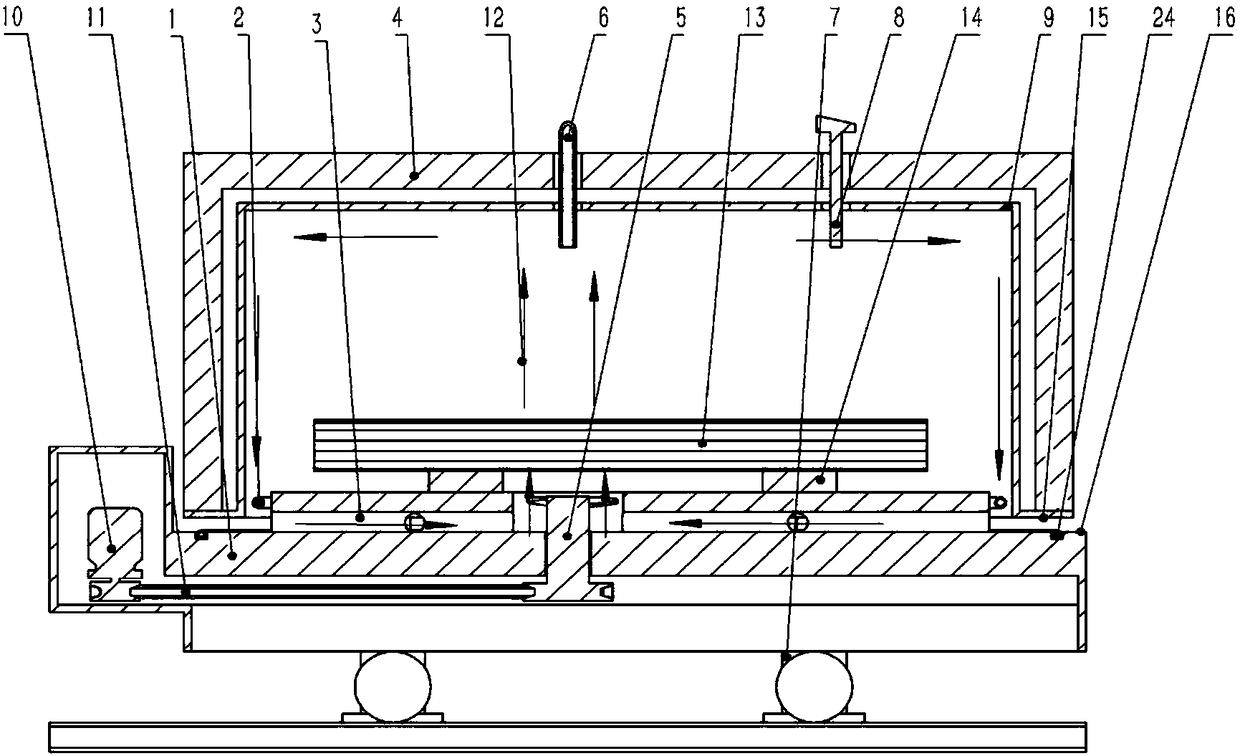
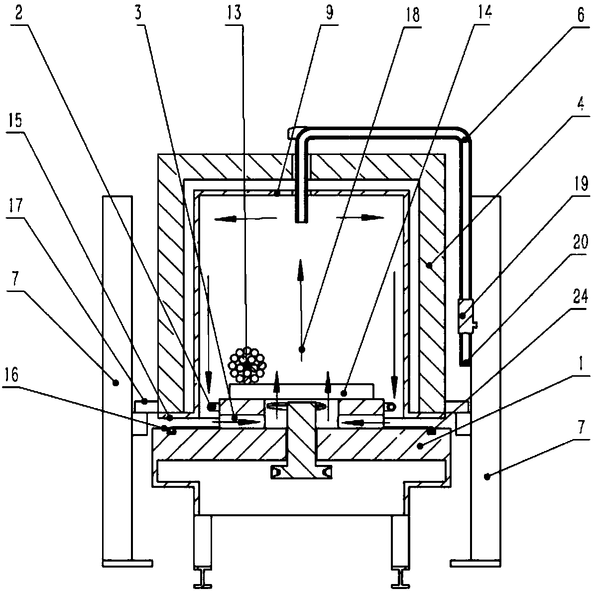
[0023] Such as Figure 1-Figure 2 As shown, the present invention provides a trolley-type annealing furnace, comprising: a trolley 1, a furnace body 4, and the furnace body 4 is sealed on the trolley 1 by fastening by its own gravity;

[0024] A motor 10 is arranged on the trolley 1, and the motor 10 is connected with an axial flow fan 5 through a triangular tape 11, and a workpiece 13 is placed above the axial flow fan 5;

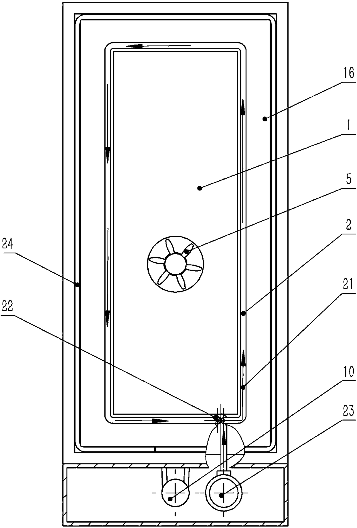
[0025] Between the workpiece 13 and the trolley sealing surface 16 of the trolley 1, a return air duct 3 is laid horizontally and vertically, and the horizontally and vertically laid return air duct 3 forms a wind tunnel at the central i...


PUM


Abstract

The invention discloses a trolley type annealing furnace. The trolley type annealing furnace comprises a trolley and a furnace body which is sealed to the trolley by means of its gravity in a tight buckling manner; a motor is arranged on the trolley, and is connected with an axial flow fan through a triangular rubber belt; a workpiece is placed above the axial flow fan; air returning pipes are laid between the workpiece and the trolley sealing face of the trolley in the transverse direction and in the vertical direction; an air tunnel is formed in the center junction position of the air returning pipes which are correspondingly laid in the transverse direction and in the vertical direction; the axial flow fan is arranged in the air tunnel; air blown out of the axial flow fan penetrates the air tunnel and then is blown to the workpiece; below the workpiece, a circle of annular cooling circulating pipe is laid around the workpiece in the furnace body; the cooling circulating pipe is connected with a variable frequency motor outside the furnace body through a pipeline; and the variable frequency motor performs cooling treatment in a hearth by means of compressed air. The trolley type annealing furnace has the beneficial effects of taking investment, running cost and workpiece quality into consideration at the same time, and being simple in structure, efficient and capable of saving energy and reducing the production cost.

Description

technical field [0001] The application belongs to the technical field of special steel heat treatment, and in particular relates to a trolley-type annealing furnace. Background technique [0002] The trolley-type annealing furnace is one of the most widely used heat treatment equipment for metal materials in metallurgy, machining, pressure processing and other processes. The trolley-type annealing furnace is the most widely used annealing furnace in the production of special steel. It can be widely used because only the trolley occupies the workshop area under the crane for a short time, and the furnace body is placed in the attached workshop and driving area, saving Nearly 60% of the annealing process occupies the main workshop investment. Different types of trolley-type annealing furnaces are formed according to regional natural gas supply conditions, production varieties and investment positioning. [0003] At present, in the process of heating the workpiece in the curr...

Claims


Application Information

Patent Timeline
Patent Type & Authority Patents(China)
IPC IPC(8): C21D1/26C21D9/00
CPCC21D1/26C21D9/00
Inventor 朱泉川李绍平李芮
Owner CHONGQING JINKAI SPECIAL STEEL PROD
Learn More