A baking structure for a display substrate
A technology for displaying substrates and substrates, which is applied in printing, printing devices, etc., and can solve problems such as the time when solvents cannot be dried, uneven display brightness, and inconsistency
- Summary
- Abstract
- Description
- Claims
- Application Information
AI Technical Summary
Problems solved by technology
Method used
Image
Examples
Embodiment 1
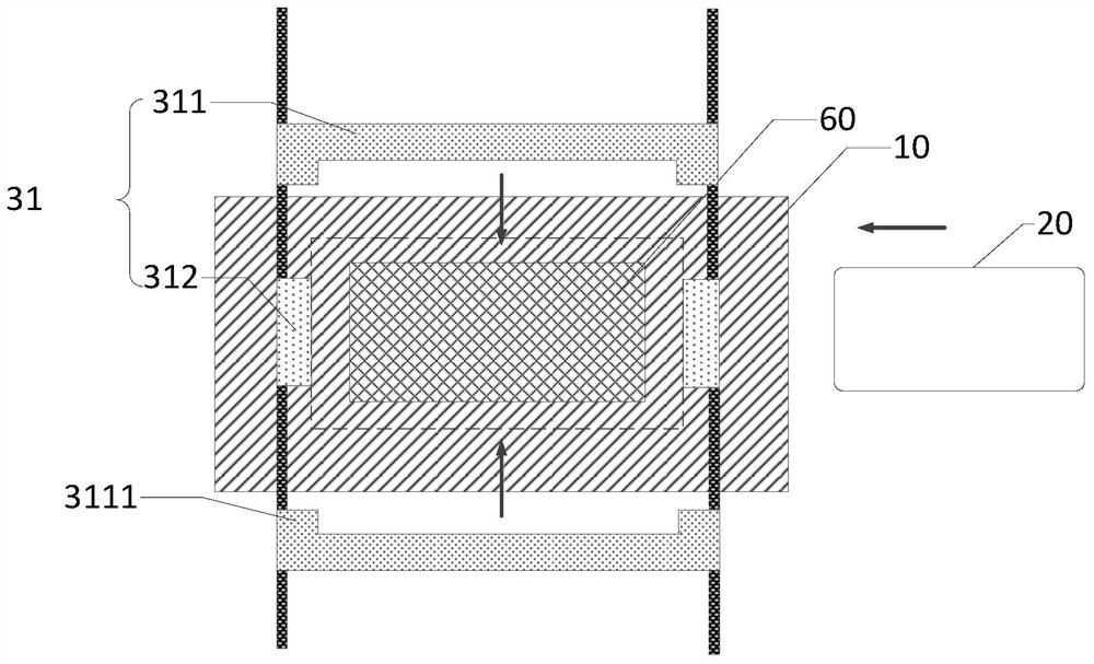
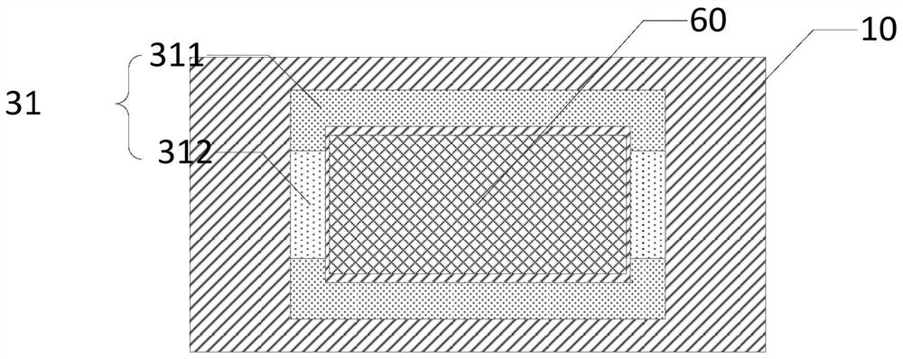
[0036] Such as figure 1 As shown, in this embodiment, the display substrate baking structure of the present invention includes a heating plate 10, a substrate 20, a retaining wall structure 30, a sliding assembly and a sliding rail.
[0037] The heating plate 10 is a heating device for displaying the baking structure of the substrate. It has a heating surface that can convert electrical energy into thermal energy to heat objects. Compared with general dyes, electric heating can obtain higher temperatures, and it is easy to realize automatic temperature control. Control and remote control, the heating method of the heating plate 10 is not limited, including but not limited to one of resistance heating, induction heating, arc heating, infrared heating and medium heating.
[0038] The substrate 20 is a rectangular glass substrate with a long side and a short side. During the inkjet printing process, the substrate 20 enters the baking region 11 from the outside of the baking regio...
Embodiment 2
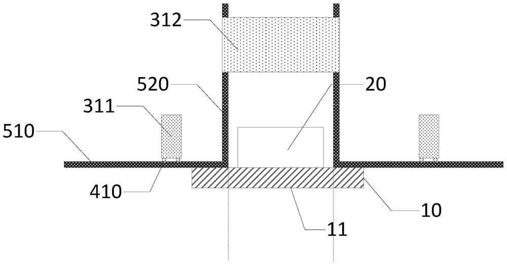
[0044] The structure of this embodiment is substantially the same as that of Embodiment 1. The difference lies in that the second retaining wall frame 312 of the present invention moves in a different way. Specifically, a sliding assembly and a slide rail are provided on the outside of the heating plate 10, and the The slide rails include two sets of parallel first linear slide rails 510, the first linear slide rails 510 are parallel to the heating surface of the heating plate 10 and located outside the baking area 11, each of the first linear slide rails 510 A linear slide rail 510 corresponds to the bottom side of the first retaining wall frame 311 , that is, the width of each set of the first linear slide rails 510 is equal to the length of the first retaining wall frame 311 . In order to enable the first retaining wall frame 311 to move on the first linear slide rail 510, the first retaining wall frame 311 and the first linear slide rail 510 are fixed with a second A slidi...
Embodiment 3
[0048] This embodiment is generally similar in structure to Embodiment 1, the difference is that the retaining wall structure 30 of the present invention adopts a fixed retaining wall structure, such as Figure 6 As shown, specifically, the retaining wall structure 30 is a welded or integrally formed quadrilateral hollow structure, and the area of the heating plate 10 inside the quadrilateral is the baking area 11. Since the retaining wall structure 30 is Fixed wall structure, so in this embodiment, the substrate 20 of the present invention enters the baking area 11 from top to bottom. In order to facilitate the substrate 20 entering the baking area 11, the substrate 20 Two grooves 32 are provided on one side of the retaining wall structure 30 corresponding to the short side of the sill, and the openings of the grooves 32 are facing away from each other, which is convenient for the manipulator to grab the substrate 20 into the baking area and position it.
PUM
| Property | Measurement | Unit |
|---|---|---|
| height | aaaaa | aaaaa |
Abstract
Description
Claims
Application Information
 - R&D
- Intellectual Property
- Life Sciences
- Materials
- Tech Scout
- Unparalleled Data Quality
- Higher Quality Content
- 60% Fewer Hallucinations
Browse by: Latest US Patents, China's latest patents, Technical Efficacy Thesaurus, Application Domain, Technology Topic, Popular Technical Reports.
© 2025 PatSnap. All rights reserved.Legal|Privacy policy|Modern Slavery Act Transparency Statement|Sitemap|About US| Contact US: help@patsnap.com


