Eureka AIR delivers breakthrough ideas for toughest innovation challenges, trusted by R&D personnel around the world.

Textile yarn separators and applied high-speed ring spinning frame thereof

A technology of yarn separator and spinning frame, which is applied in spinning frame, continuous winding spinning frame, textile and paper making, etc., can solve the problems of yarn breakage and end breakage, reduce end breakage and improve use efficiency. , the effect of increasing the height and width

Pending Publication Date: 2017-10-24
JINGWEI TEXTILE MASCH CO LTD
View PDF11 Cites 0 Cited by
  • Summary
  • Abstract
  • Description
  • Claims
  • Application Information

AI Technical Summary

Problems solved by technology

[0004] However, during the spinning process, due to the increase of the spindle speed, the number of yarn breakages will increase, and the yarn will be wound on the yarn guide hook or at the bottom of the bobbin. Smaller, the broken yarn will pass around the yarn partition, interrupting the yarn of the adjacent spindle, causing the yarn breakage of the adjacent spindle, and even causing a large area of ​​broken ends

Method used

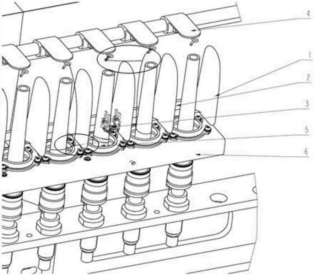
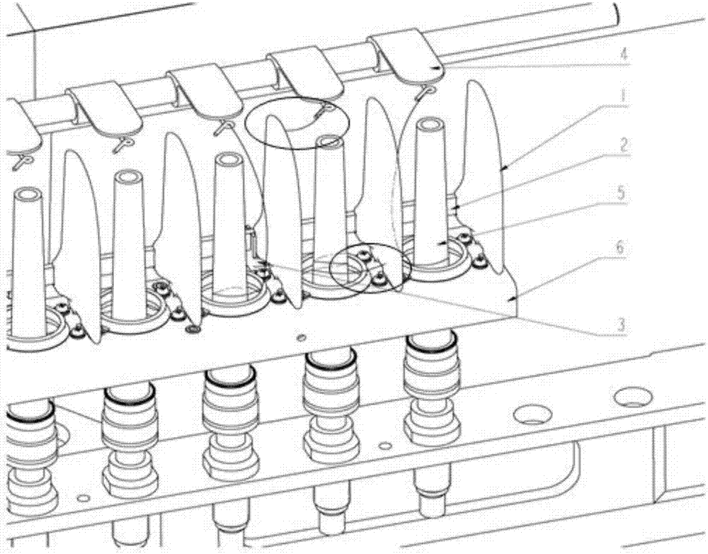
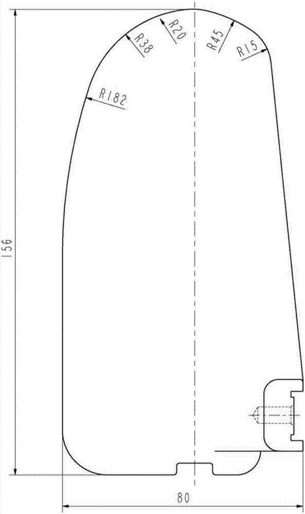

Image

  • Textile yarn separators and applied high-speed ring spinning frame thereof
  • Textile yarn separators and applied high-speed ring spinning frame thereof
  • Textile yarn separators and applied high-speed ring spinning frame thereof

Examples


Embodiment Construction

[0018] It should be noted that, in the case of no conflict, the embodiments in the present application and the features in the embodiments can be combined with each other. The present invention will be described in detail below with reference to the accompanying drawings and examples.

[0019] In order to enable those skilled in the art to better understand the solution of the present application, the technical solution in the embodiment of the application will be clearly and completely described below in conjunction with the accompanying drawings in the embodiment of the application. Obviously, the described embodiment is only It is an embodiment of a part of the application, but not all of the embodiments. Based on the embodiments in this application, all other embodiments obtained by persons of ordinary skill in the art without creative efforts shall fall within the scope of protection of this application.

[0020] Such as figure 1 As shown in -3, the present invention pr...


PUM

PropertyMeasurementUnit
heightaaaaaaaaaa

Abstract

The invention relates to textile yarn separators, and the textile yarn separators are suitable for a ring spinning frame. The yarn separators are evenly distributed on a yarn guide flat steel, the yarn guide flat steel is fixed to flat iron bases of the yarn separators, and the upper portions of the yarn separators are arc segments; the arc segments are formed by several small arcs in a transition mode, the lower portions of the yarn separators are wider than the upper portions of the yarn separators, the width of the lower portions of the yarn separators is 80 mm, and the whole height of the yarn separators is 156mm. The height and width of the yarn separators are increased, so that the protection area is increased, adjacent yarn cannot interfere with each other on a broken end portion, the incidence of broken ends is effectively reduced, the labor intensity of spun yarn textile workers is lowered at the same time, the use efficiency of raw materials is improved, and the economic benefits are increased; the material quality of the yarn separators is further improved, zinc-aluminium alloys are adopted for novel yarn separators, and the intensity and tenacity of the novel yarn separators are better than those of original yarn separators; the surfaces of the yarn separators are sprayed and coated with anti-static flat powder, so that the anti-static effect is greatly improved, and the adherence of the surfaces of the yarn separators for flying flowers is avoided.

Description

technical field [0001] The invention relates to the field of textile machinery, in particular to a yarn spacer for textile and a high-speed ring spinning machine for its application. Background technique [0002] Ring spinning frame is an important equipment with large volume and wide range in the production process of textile industry. At present, the technical requirements based on this equipment are getting higher and higher. Most textile enterprises, especially large-scale enterprises, are moving the research and development direction of ring spinning machine equipment towards automation, continuous, especially high-speed direction. develop. [0003] Based on the above-mentioned development trend, textile mills began to increase the spindle speed requirements for ring spinning frames, that is, from the original 16,000 rpm to 22,000 rpm, and some textile enterprises even reached 25,000 rpm. [0004] However, during the spinning process, due to the increase of the spindl...

Claims


Application Information

Patent Timeline
Patent Type & Authority Applications(China)
IPC IPC(8): D01H1/42
CPCD01H1/422
Inventor 姚志国孙照杰薛飞龙王磊刘凯王翠红侯喜凤张肇娟
Owner JINGWEI TEXTILE MASCH CO LTD
Why Eureka
Eureka Blog
Learn More