

Burner propelling system
A propulsion system and burner technology, applied in the field of hazardous waste incineration treatment, can solve the problems of increased energy consumption, coking blockage, cumbersomeness, etc., and achieve the effect of reducing labor costs and energy consumption
- Summary
- Abstract
- Description
- Claims
- Application Information
AI Technical Summary
Problems solved by technology
Method used
Image

Examples
Embodiment 1
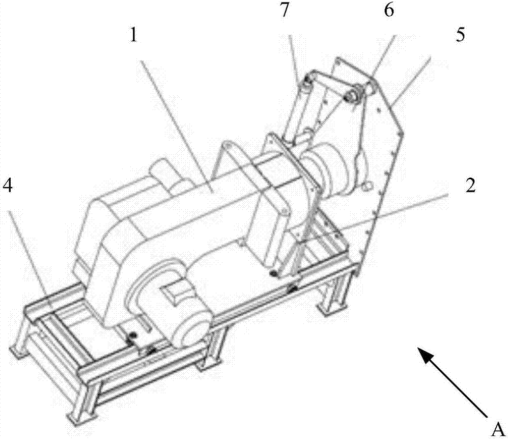
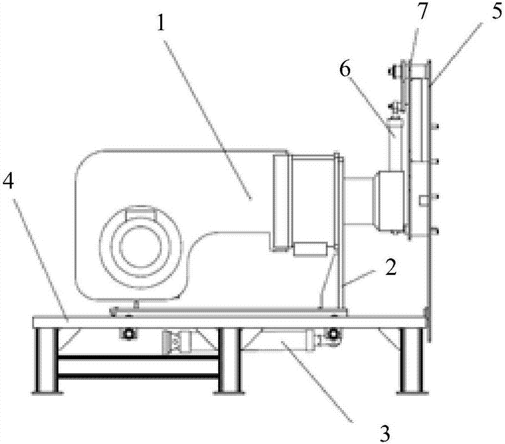
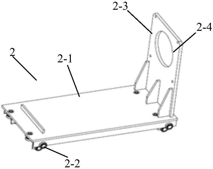
[0045] Refer below Figure 1A , Figure 1B , figure 2 , image 3 , Figure 4A and Figure 4B The burner propulsion mechanism of the present invention is described; wherein, Figure 1A A schematic diagram of a three-dimensional structure of a combustor propulsion system according to an embodiment of the present invention, Figure 1B based on Figure 1A The side schematic diagram of the combustor propulsion system viewed along the direction A in the figure; figure 2 A schematic structural diagram of a sliding device according to an embodiment of the present invention; image 3 It is a schematic structural diagram of a stent according to an embodiment of the present invention; Figure 4A A schematic diagram of the structure of the movable cover in the open position of the cover according to an embodiment of the present invention; and Figure 4B It is a structural schematic diagram of the movable cover in the closed position of the cover according to an embodiment of the p...
PUM
 Abstract
Description
Claims
Application Information