
Linear vacuum on-load dual-position switch

A gear shifting and switch switching technology, which is applied in the direction of electric switches, electrical components, circuits, etc., can solve the problems of reduced contact conductivity, generation of tip discharge, and increased contact resistance, so as to achieve easy installation and maintenance, and prevent arcing The effect of drawing arc and improving service life

Active Publication Date: 2020-07-24
宁波安德奥电力设备有限公司
View PDF6 Cites 0 Cited by
  • Summary
  • Abstract
  • Description
  • Claims
  • Application Information

AI Technical Summary

Problems solved by technology

[0003] The on-load tap-changer used in the power supply department is also a kind of switch. Because the power supply department needs to keep the circuit working continuously when switching circuits and adjusting voltage and load, the traditional switch is not competent.
[0004] In addition, at the moment when the circuit is closed and switched, due to the potential difference between the moving contact and the static contact, when they are close to each other, a tip discharge phenomenon will occur, and then air ionization will occur, and the arc will produce high-temperature oxidation on the surface of the contact. The conductivity of the contact decreases and the contact resistance increases. In the case of high current, once the contact resistance increases, the heating power P is proportional to the contact resistance, and the contact resistance generates serious heat, which further deteriorates the working state of the contact point.

Method used


Image

  • Linear vacuum on-load dual-position switch
  • Linear vacuum on-load dual-position switch
  • Linear vacuum on-load dual-position switch

Examples


Embodiment Construction

[0030] Embodiments of the present invention will be further described below in conjunction with the accompanying drawings.

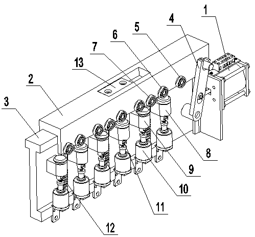
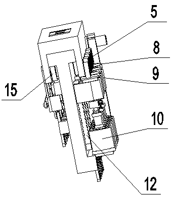
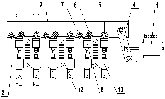
[0031] like figure 1 and figure 2 As shown, the linear permanent magnet vacuum on-load changeover switch described in the present invention, such as Figure 7 and Figure 8 The base 3 is fixedly connected with the base of the device. There is a T-shaped slide rail above the base, which cooperates with the chute under the sliding block.

[0032] The moving mechanism adopted by the switching mechanism is a permanent magnet mechanism 1. The permanent magnet mechanism itself is an electromagnetic switch with a return spring. The coil is energized to generate a magnetic field, which attracts the permanent magnet, overcomes the elastic force of the return spring, and reverses the movement of the permanent magnet mechanism. The rod is pulled to one side; the coil is de-energized, and the moving rod of the permanent magnet mechanism returns to the initial ...


PUM


Abstract

The invention provides a linear vacuum on-load dual-gear selector switch. A sliding block is in sliding connection with the top of a base. A limit limiting mechanism is arranged on the sliding block. The sliding block is connected with a permanent magnet mechanism. One side of the sliding block is provided with a roller, and the other side of the sliding block is provided with a movable contact mounting base. One side of the base, relative to the roller, is provided with a vacuum tube buffer, a main vacuum tube, an auxiliary vacuum tube and a transition resistor. The other side of the base, relative to the movable contact mounting base, is provided with a static contact set of the selector switch. The static contact set comprises two static contacts, and a neutral position gear is arranged between the two static contacts. By the selector switch, the gear switching function and the vacuum arc extinguishing function of the selector switch can be completed at the same time. Meanwhile, during the switching process, the circuit is continuously powered on. By adopting the linear switching mode, the installation volume of the selector switch can be reduced, and the switching speed of the selector switch is high. Meanwhile, the selector switch is high in reliability, and long in service life.

Description

technical field [0001] The invention relates to an on-load changeover switch, in particular to a vacuum on-load double-position changeover switch with a linear structure. Background technique [0002] There are many uses for a toggle switch, from the simplest light switch to complex high-speed switches, time-delay switches, etc., are different types of toggle switches, which allow circuits to quickly switch between two or three states, including closed and open two ways. [0003] The on-load tap changer used in the power supply department is also a kind of switch. Because the power supply department needs to keep the circuit working continuously when switching circuits and adjusting voltage and load, the traditional switch is not competent. [0004] In addition, at the moment when the circuit is closed and switched, due to the potential difference between the moving contact and the static contact, when they are close to each other, a tip discharge phenomenon will occur, and...

Claims


Application Information

Patent Timeline
Patent Type & Authority Patents(China)
IPC IPC(8): H01H9/00
CPCH01H9/0027H01H9/0038
Inventor 史伟峰
Owner 宁波安德奥电力设备有限公司
Learn More