Combined intelligent capacitor

A capacitor and combined technology, applied in the field of capacitors, can solve the problems of narrow spacing between parallel electrical appliances, easy heat damage and other problems, and achieve the effect of solving the problem of installation space, simple overall structure and simple wiring

CN107294113AInactive Publication Date: 2017-10-24安徽航睿电子科技有限公司
1 Cites 2 Cited by

Patent Information

Authority / Receiving Office
CN · China
Patent Type
Applications(China)
Current Assignee / Owner
Publication Date
2017-10-24
Estimated Expiration
Not applicable · inactive patent

Smart Images

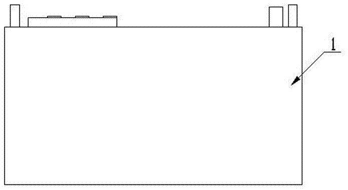
  • Figure 1
    Figure 1
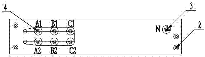
  • Figure 2
    Figure 2
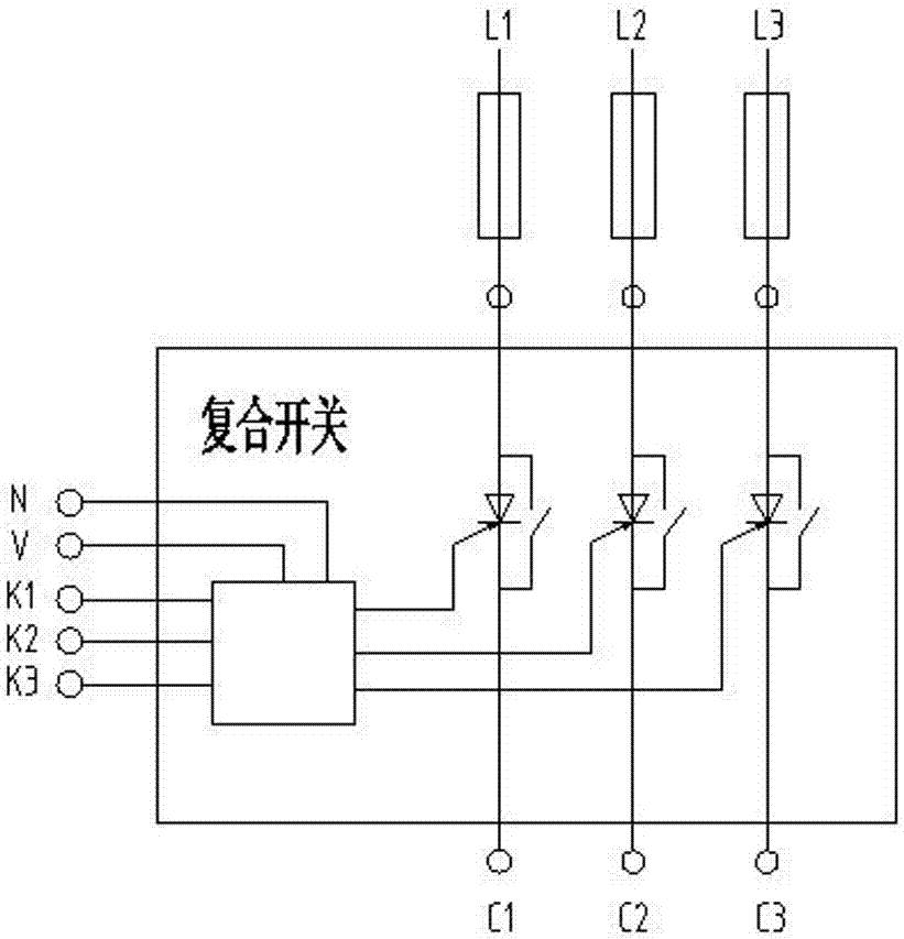
  • Figure 3
    Figure 3
Patent Text Reader

Abstract

The invention discloses a combined intelligent capacitor and relates to the technical field of capacitors. The combined intelligent capacitor comprises a shell, a wiring terminal, a separating compensation capacitor zero-phase output end and a three-phase capacitor output end, wherein the three-phase capacitor output end is arranged at one side of the top end of the shell and the wiring terminal and the separating compensation capacitor zero-phase output end is arranged at the other side of the top end of the shell; a compound switch is arranged in the shell; three-phase input ends L1, L2 and L3 of the compound switch are connected to a power grid and three-phase output ends C1, C2 and C3 are connected to a capacitor or an electric reactor; a co-compensation switch is only connected to a separating compensation switch K1 to control three-phase output; the separating compensation switch K1 controls output of the C1, K2 controls the output of the C2 and K3 controls the output of the C3; V is connected to an anode at the public end of a control signal; and N is a power grid null line input end. The combined intelligent capacitor has simple overall structure and simple wiring, a problem of hybrid compensation installation space is solved, and meanwhile, the problems of narrow distance between parallel electric appliance groups and easiness in heating and damage are solved, the speed of discharge can be accelerated, and the conditions are created for quick switching of the capacitor.
Need to check novelty before this filing date? Find Prior Art

Description

technical field

[0001] The invention relates to the technical field of capacitors, in particular to a combined smart capacitor. Background technique

[0002] At present, the smart capacitors commonly used are mostly one capacitor unit, and the shell generally has a relatively large reserved space. If the core group is placed unbalanced, long-term accumulation will lead to serious internal energy accumulation, and the explosion-proof mechanism will not start. The risk of breaking down the capacitor core or causing the assembled capacitor to bulge and even cause a fire is increased. In addition, the problems and causes of the traditional low-voltage reactive power compensation system: large volume, poor heat dissipation of the whole cabinet, once the product is formed, it is inconvenient to expand.

[0003] Due to the current power grid operation process, it is very easy to have three-phase unbalanced phenomena. For example, if a single AC contactor device with the same input...

Examples

Embodiment Construction

[0010] see Figure 1-3 , the combined smart capacitor is realized through the following technical solutions: it includes a shell 1, a terminal 2, a sub-compensation capacitor zero-phase output end 3, and a three-phase capacitor output end 4 manufactured by a special mold, and the shell 1 The top side is provided with a three-phase capacitor output terminal 4, and the other end is provided with a binding post 2 and a zero-phase output terminal 3 of the sub-compensation capacitor. A composite switch is provided inside the housing 1, and the three-phase input terminals L1, L2, L3 is connected to the power grid, and C1, C2, and C3 at the three-phase output end are connected to capacitors or reactors. The common compensation switch is only connected to the distribution switch K1 to control the three-phase output. The distribution switch K1 controls the output of C1, K2 controls the output of C2, and K3 controls C3. Output, V is connected to the positive pole of the common terminal ...