Control method, apparatus and equipment of PFC circuit, and storage medium
A control method and technology of a control device, which are applied to output power conversion devices, electrical components, high-efficiency power electronic conversion, etc., can solve problems such as the inability to accurately realize the current loop control process, and achieve the purpose of preventing erroneous actions, suppressing harmonic components, The effect of ensuring power quality
- Summary
- Abstract
- Description
- Claims
- Application Information
AI Technical Summary
Problems solved by technology
Method used
Image

Examples
Embodiment 1
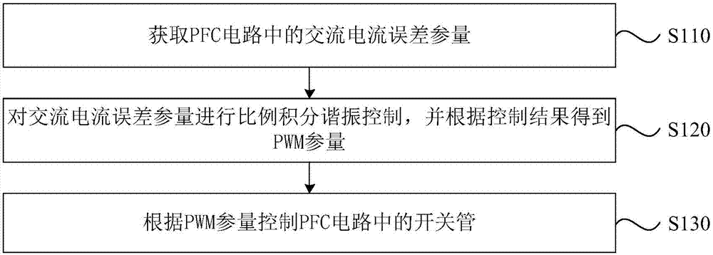
[0035] figure 1 It is a flow chart of a method for controlling a PFC circuit provided by Embodiment 1 of the present invention. The control method of the PFC circuit provided in this embodiment is applicable to the situation where the double closed-loop control of the outer voltage loop and the inner current loop is performed on the PFC circuit. The control method of the PFC circuit provided in this embodiment can be executed by a control device of the PFC circuit, and the control device can be implemented in the form of software and / or hardware, and integrated into the control device of the PFC circuit.
[0036] refer to figure 1 The control method of the PFC circuit provided in this embodiment specifically includes:
[0037] S110. Obtain an AC current error parameter in the PFC circuit.
[0038] Exemplarily, the PFC circuit may be a half-wave rectification circuit, or a bridge rectification circuit. The PFC circuit includes a DC signal and an AC signal, and the PFC circu...
Embodiment 2
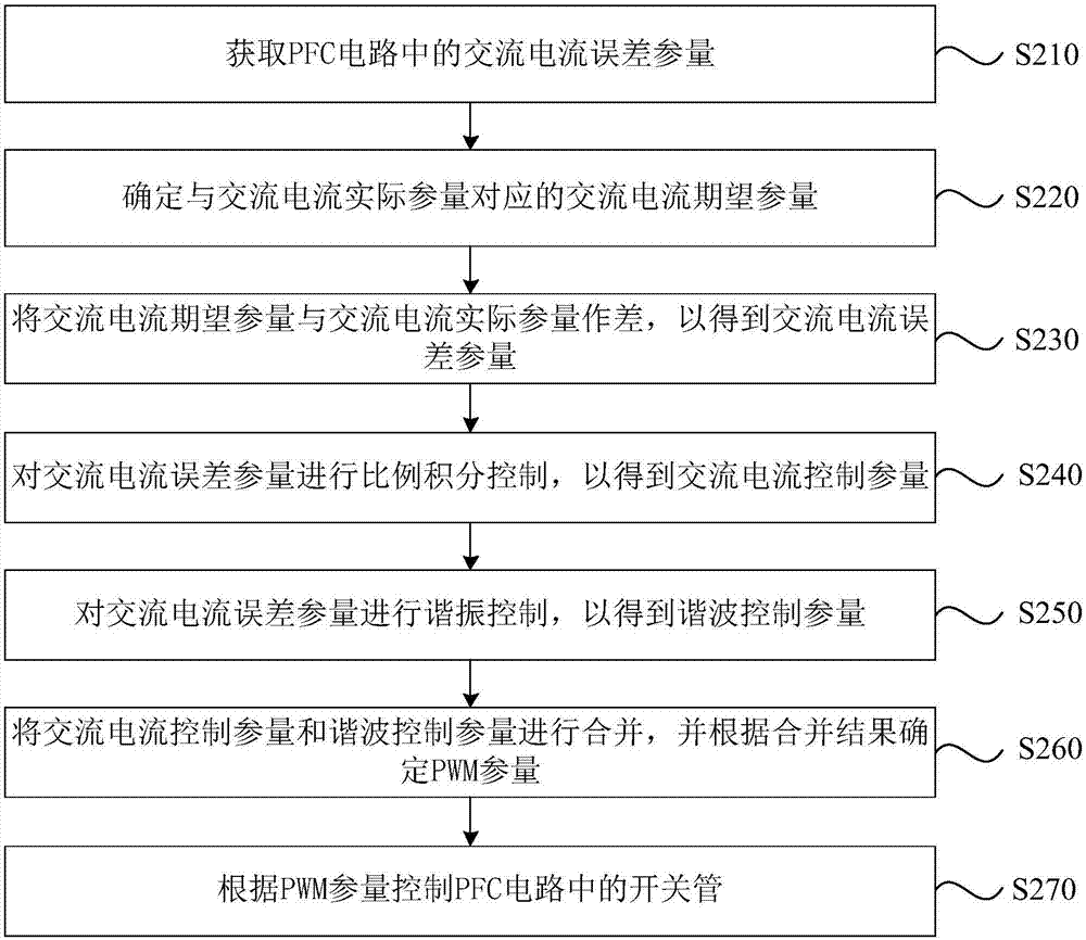
[0051] Figure 2a It is a flow chart of a method for controlling a PFC circuit provided by Embodiment 2 of the present invention. This embodiment is embodied on the basis of the above-mentioned embodiments. Specifically, refer to Figure 2a A method for controlling a PFC circuit provided in this embodiment specifically includes:
[0052] S210. Obtain an actual AC current parameter in the PFC circuit.
[0053] S220. Determine an expected AC current parameter corresponding to an actual AC current parameter.
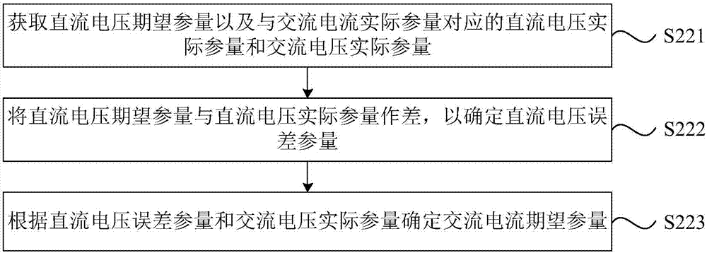
[0054] Specifically, in the PFC circuit, the actual AC current parameter at each moment has a corresponding expected AC current parameter. Among them, refer to Figure 2b , the method for determining the expected parameter of the alternating current specifically includes:
[0055] S221. Obtain an expected DC voltage parameter and an actual DC voltage parameter and an actual AC voltage parameter corresponding to the actual AC current parameter.
[0056] Wherein, the e...
Embodiment 3
[0088] image 3 It is a schematic structural diagram of a control device for a PFC circuit provided by Embodiment 3 of the present invention. The control device for the PFC circuit provided in this embodiment specifically includes: an acquisition module 301 , a modulation module 302 and a control module 303 .
[0089] Wherein, the acquisition module 301 is used to obtain the AC current error parameter in the PFC circuit; the modulation module 302 is used to perform proportional integral resonance control on the AC current error parameter, and obtains the PWM parameter according to the control result; the control module 303 is used to obtain the PWM parameter according to The PWM parameter controls the switching tube in the PFC circuit.
[0090] To sum up, by obtaining the AC current error parameters in the PFC circuit, and performing proportional integral resonance control on the AC current error parameters, effective control of the harmonic components in the AC current error...
PUM
 Abstract
Description
Claims
Application Information
PatSnap Eureka turns technology decisions into work you can execute. Powered by our Innovation Knowledge Graph, it runs expert workflows across engineering, life sciences, materials and intellectual property. Get your review-ready output in minutes.


