Phase difference compensation membrane manufacturing equipment and method

A production method and compensation film technology, which is applied in the field of phase difference compensation film production equipment, can solve the problems of high scrap rate, poor stretching accuracy, and complex structure, and achieve the effects of reducing scrap rate, high stretching accuracy, and simplifying the structure

Active Publication Date: 2017-10-27
深圳市鑫友道科技有限公司
View PDF3 Cites 1 Cited by
  • Summary
  • Abstract
  • Description
  • Claims
  • Application Information

AI Technical Summary

Problems solved by technology

[0004] In order to make the optical film have a phase difference, it is necessary to use a stretching mechanism to stretch the base film. The existing stretching equipment is either complex in structure, or has poor stretching accuracy and high scrap rate.

Method used


Image

  • Phase difference compensation membrane manufacturing equipment and method
  • Phase difference compensation membrane manufacturing equipment and method
  • Phase difference compensation membrane manufacturing equipment and method

Examples


Embodiment 1

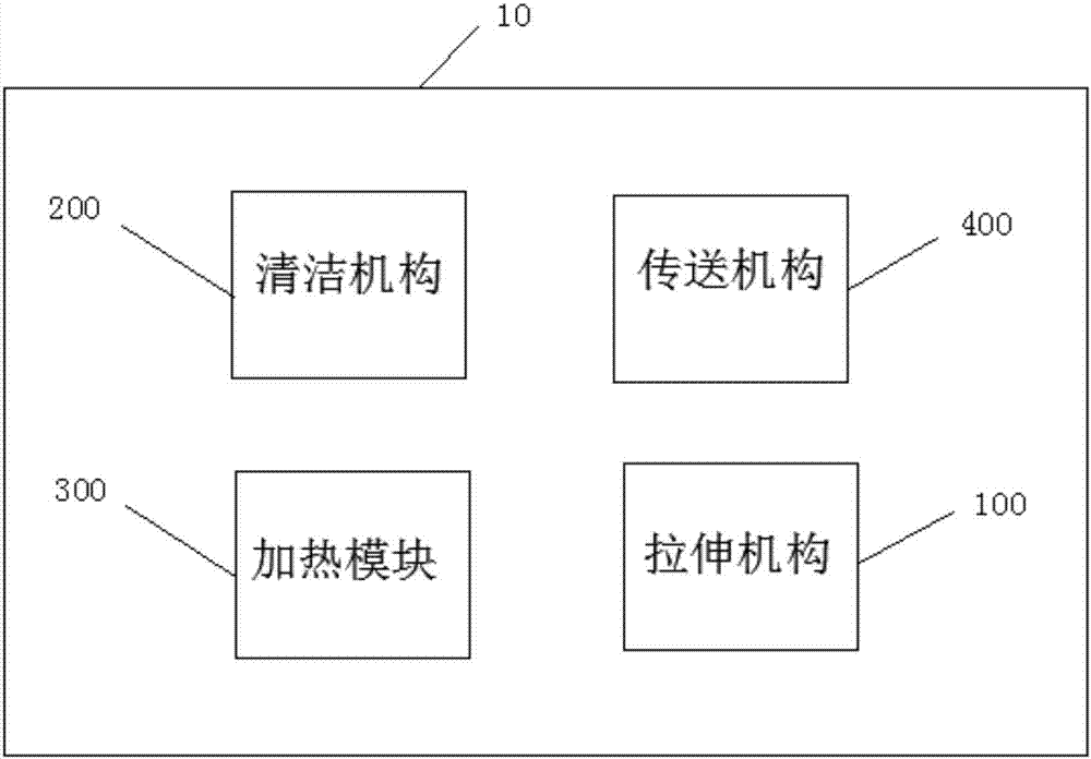
[0047] see figure 1 , figure 2 , the present embodiment provides a retardation compensation film manufacturing device 10 and a method, regarding the retardation compensation film manufacturing device 10 . It includes a cleaning mechanism 200 , a heating box, a stretching mechanism and a transport mechanism 400 .

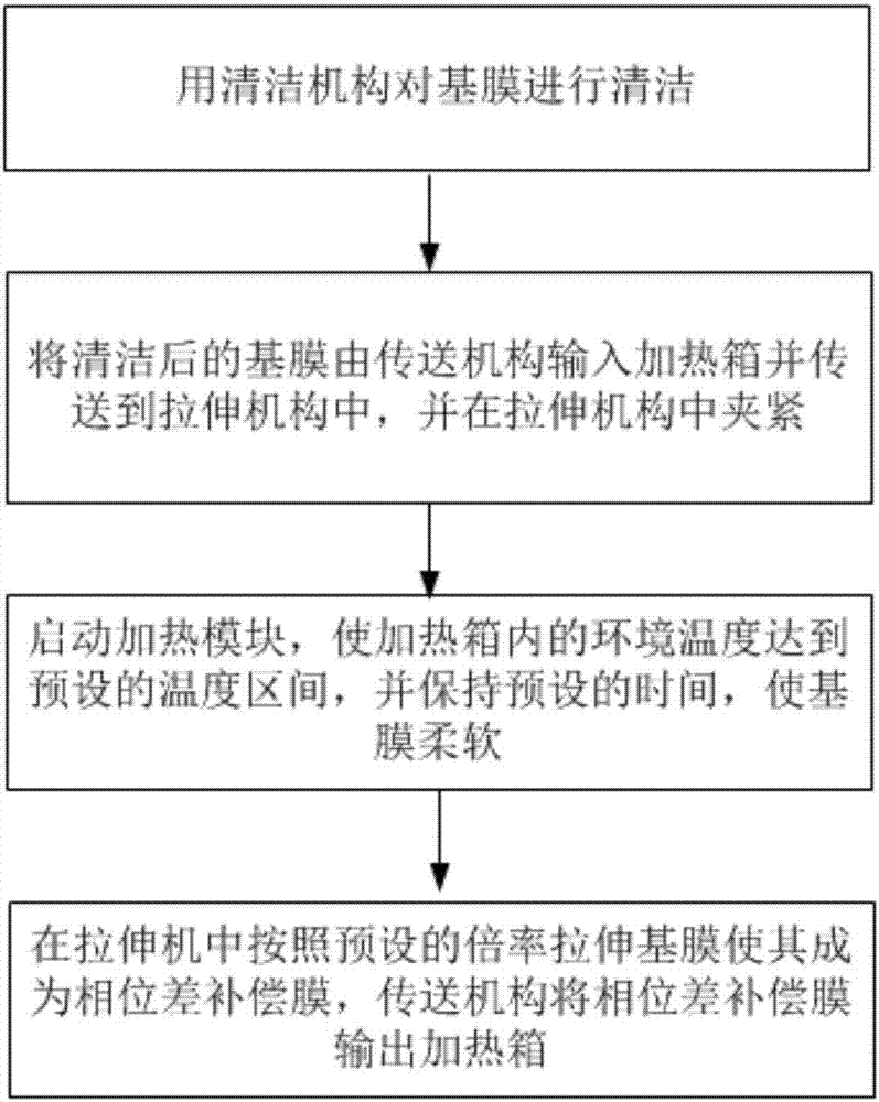
[0048] Wherein, the cleaning mechanism 200 is arranged outside the heating box, and the cleaning mechanism 200 is used to clean the base film. A heating module 300, a transmission mechanism 400 and a stretching mechanism are arranged in the heating box. The stretching mechanism is used to stretch the heated base film according to a preset ratio to make it a retardation compensation film. The transmission mechanism 400 is used to clean the The final base film is input into the stretching mechanism and the phase difference compensation film formed after stretching is output to the heating box.

[0049] As a preferred conveying mechanism 400, it includes multiple pa...

Embodiment 2

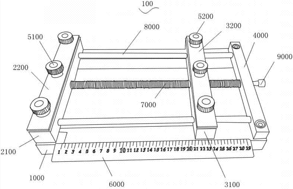
[0083] see image 3 , the present embodiment provides a retardation compensation film production equipment 10, compared with the embodiment 1, the main difference of the present embodiment is:

[0084] The first fixing plate 2100 is provided with a second threaded hole matched with the screw rod;

[0085] And / or, the fixing base 4000 is provided with a third threaded hole matched with the screw rod.

[0086] In Embodiment 1, the first fixing plate 2100 and the fixing seat 4000 cooperate with the screw rods to be bearings.

[0087] When the first fixing plate 2100 is provided with a second threaded hole cooperating with the screw rod, and the fixing base 4000 is provided with a third threaded hole cooperating with the screw rod. The screw rod is threadedly connected with the first fixing plate 2100 and the fixing seat 4000, and when the screw rod rotates, it will extend into or out from the second threaded hole and the third threaded hole.

[0088] Other features in this embod...


PUM


Abstract

The invention provides phase difference compensation membrane manufacturing equipment and method. The equipment comprises a cleaning mechanism and a heating tank, wherein the heating tank is internally provided with a heating module, a conveying mechanism and a tension mechanism. The method comprises the following steps implemented by using the equipment: cleaning a base membrane by using the cleaning mechanism; feeding the cleaned base membrane into the heating tank and the tension mechanism through the conveying mechanism, and clamping the base membrane in the tension mechanism; powering on the heating module, increasing the ambient temperature inside the heating tank to a preset temperature section, and keeping the temperature for a preset time so as to soften the base membrane; drawing the base membrane in the tension mechanism according to preset multiplying power so as to obtain a phase difference compensation membrane, and discharging the phase difference compensation membrane outside the heating tank through the conveying mechanism. As the base membrane is directly drawn in the heating tank, and the heating temperature and the heating time are preset, the rejection rate is reduced, and the manufacturing time is shortened. Furthermore, the structure of the tension mechanism is simplified, and the tension precision is high.

Description

technical field [0001] The invention relates to the field of stretching processing equipment, in particular, to a phase difference compensation film production equipment and method. Background technique [0002] In recent years, with the enlargement of the screen of liquid crystal display devices and the expansion of the use environment, the requirements for visibility (brighter, easier to see, better contrast, higher viewing angle, etc.) have also become stricter. However, improvement of the liquid crystal cell itself cannot sufficiently satisfy the requirement for improvement of visibility, and therefore largely depends on performance improvement of optical films such as retardation compensation films. [0003] Therefore, in optical films such as phase difference compensation films, high transparency, low photoelasticity, heat resistance, light resistance, high surface hardness, high mechanical strength, large phase difference, and small wavelength dependence of phase diff...

Claims


Application Information

Patent Timeline
Patent Type & Authority Applications(China)
IPC IPC(8): B29C55/04B29C55/20B29L11/00
CPCB29C55/04B29C55/20B29L2011/00
Inventor 杨勇
Owner 深圳市鑫友道科技有限公司
Why Eureka
Try Eureka