
Tube-in-tube spiral-plate heat exchanger

A technology of spiral plates and heat exchangers, applied in the direction of heat exchanger types, heat exchanger shells, indirect heat exchangers, etc., can solve the problems of large space occupation and inconvenient use, so as to improve efficiency and save space The effect of occupying and simplifying the process flow

Pending Publication Date: 2017-10-27
SHANGHAI LANBIN PETROCHEM EQUIP +1
View PDF3 Cites 0 Cited by
  • Summary
  • Abstract
  • Description
  • Claims
  • Application Information

AI Technical Summary

Problems solved by technology

[0004] In order to solve the problem that the existing spiral plate heat exchanger takes up a large space and is inconvenient to use, the present invention proposes a casing type spiral plate heat exchanger

Method used


Image

  • Tube-in-tube spiral-plate heat exchanger
  • Tube-in-tube spiral-plate heat exchanger
  • Tube-in-tube spiral-plate heat exchanger

Examples


Embodiment Construction

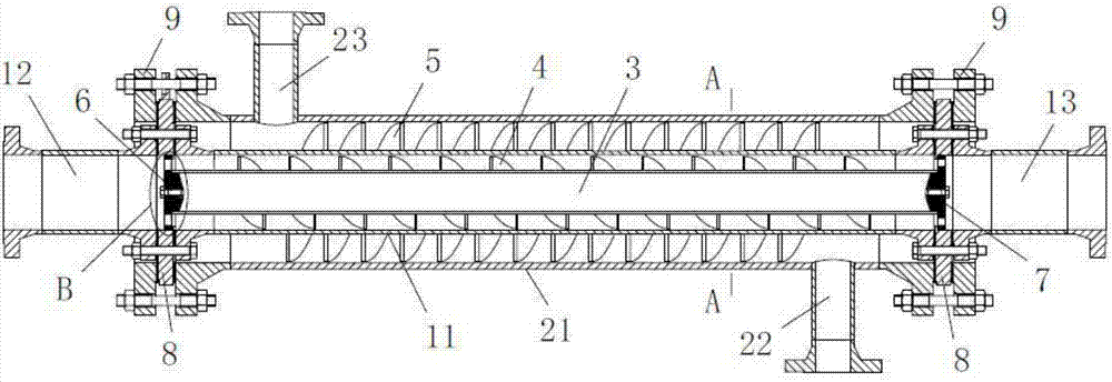
[0023] The technical solutions of the present invention will be described in detail below in conjunction with the accompanying drawings.

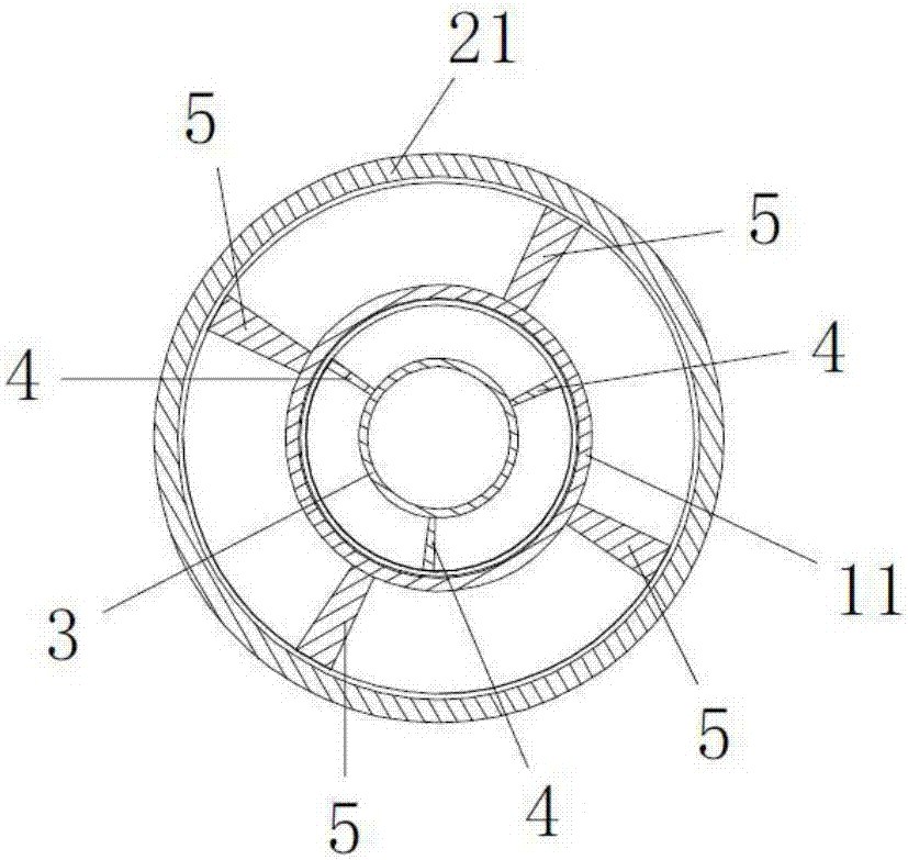
[0024] combine figure 1 As shown, the casing-type spiral plate heat exchanger of the present invention includes a tube-side assembly and a shell-side assembly. The tube assembly includes a tube 11 , a tube inlet 12 and a tube outlet 13 , and the tube inlet 12 , the tube outlet 13 and the tube 11 are arranged along the same straight line. The shell-side assembly includes a shell-side tube 21, a shell-side inlet 22 and a shell-side outlet 23, wherein the shell-side tube 21 is sleeved outside the tube-side tube 11, forming a closed space between the shell-side tube 21 and the tube-side tube 11 , and the shell-side inlet 22 and the shell-side outlet 23 are used as the inlet and outlet of the confined space.

[0025] Because the tube-side inlet 12, the tube-side outlet 13 and the tube-side tube 11 are located on the same straight line, after t...


PUM


Abstract

The invention belongs to the technical field of heat exchangers and particularly relates to a tube-in-tube spiral-plate heat exchanger. In order to solve the problem that the existing spiral-plate heat exchanger uses large space in use and is convenient to use, the invention discloses a tube-in-tube spiral-plate heat exchanger, comprising a tube side component and a shell side component, wherein the tube side component comprises a tube side tube, a tube side inlet and a tube side outlet which are positioned on a same line, the tube side component includes a shell side tube, a shell side inlet and a shell side outlet, and the shell side tube sleeves the tube side tube. The tube-in-tube spiral-plate heat exchanger is simple in structure and can be serially connected and mounted directly in a pipeline so that less space is used during mounting; the tube-in-tube spiral-plate heat exchanger can also provide heat exchanging for a medium during pipeline transport, the process flow is shortened, and heat exchanging efficiency is improved.

Description

technical field [0001] The invention belongs to the technical field of heat exchangers, in particular to a casing type spiral plate heat exchanger. Background technique [0002] A heat exchanger is an energy-saving device that transfers heat between materials between two or more fluids at different temperatures. It transfers heat from a fluid with a higher temperature to a fluid with a lower temperature, so that the fluid temperature reaches the process The specified index is to meet the needs of the process conditions, and it is also one of the main equipment to improve energy utilization. [0003] Currently, the most common heat exchanger on the market is the shell and tube heat exchanger. However, the conventional shell-and-tube heat exchanger has the problems of low heat exchange efficiency, large amount of consumables, and frequent cleaning, otherwise it will cause blockage. The spiral plate heat exchanger is a new type of heat exchanger developed in recent years. Co...

Claims


Application Information

Patent Timeline
Patent Type & Authority Applications(China)
IPC IPC(8): F28D7/10F28F9/22
CPCF28D7/10F28F9/22F28F2009/222
Inventor 张尚文郑意贺鹤荀娇徐文芳吕甜甜侯艳齐杨文光何义明谢腾腾李海涛李金波
Owner SHANGHAI LANBIN PETROCHEM EQUIP
Learn More