CT scanning X-ray source tube current modulating method and computed tomography device

A technology of current modulation and CT scanning, which is applied in computerized tomography scanners, diagnosis, echo tomography, etc., to achieve the effect of reducing X-ray radiation dose

Active Publication Date: 2017-10-31
SHANGHAI UNITED IMAGING HEALTHCARE
View PDF7 Cites 5 Cited by
  • Summary
  • Abstract
  • Description
  • Claims
  • Application Information

AI Technical Summary

Problems solved by technology

[0007] Although a lower X-ray radiation dose is used when the cardiac motion of the cardiac scan is large, due to the limitation of the hardware modulation capability of the X-ray source, it takes a certain time for the tube current of the X-ray source to rise or fall, so in order to It is ensured that the tube curren

Method used


Image

  • CT scanning X-ray source tube current modulating method and computed tomography device
  • CT scanning X-ray source tube current modulating method and computed tomography device
  • CT scanning X-ray source tube current modulating method and computed tomography device

Examples


Example Embodiment

[0080] Example 1

[0081] The following specifically describes the method for determining the target tube current by looking up the table in the above step S03.

[0082] In this embodiment, the tube currents at the beginning and end of the second period of the current heartbeat cycle are the same.
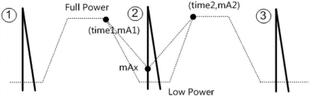
[0083] Figure 4 is a flow chart of the method for determining the target tube current in a look-up table manner according to an embodiment, such as Figure 4 shown, time 1 Represents the end time of the first period of the current heartbeat cycle, that is, the start time of the second period of the current heartbeat cycle; time 2 Indicates the start time of the first period of the next heartbeat cycle, that is, the start time of the second period of the current heartbeat cycle; mA 1 It represents the tube current at the beginning and end of the second period of the current heartbeat cycle, ie the tube current at the end of the first period of the current heartbeat cycle and ...

Example Embodiment

[0088] Embodiment 2

[0089] Image 6 It is a flowchart of another embodiment of the method for determining the target tube current by means of a lookup table. Different from the first embodiment, in this embodiment, the tube currents at the beginning and the end of the second period are different, and the value at the beginning of the second period is different. Tube current mA 1 less than the tube current mA at the end of the second period 2 .

[0090] like Image 6 shown, time 1 Indicates the end time of the first period of the current heartbeat cycle, that is, the start time of the second period of the current heartbeat cycle, mA 1 means time 1Tube current at time; time 2 Indicates the start time of the first period of the next heartbeat cycle, that is, the end time of the second period of the current heartbeat cycle, mA 2 means time 2 time tube current. It needs to be within the second period of the current heartbeat cycle (time 2 -time 1 ) will change the t...


PUM


Abstract

The invention provides a CT scanning X-ray source tube current modulating method and a computed tomography device. The method comprises the following steps: determining a heartbeat cycle in accordance with electrocardiogram signals, wherein each heartbeat cycle comprises a first period that cardiac motion is gentle and a second period that the cardiac motion is vigorous; determining target tube current within the second period of the current heartbeat cycle in accordance with tube current at the end of the period of the current heartbeat cycle which is determined in advance, tube current at the beginning of the first period of a next heartbeat cycle and pre-saved X-ray source characteristics; and controlling tube current of the X-ray source within the second period of the current heartbeat cycle, wherein the tube current within the second period of the current heartbeat cycle is greater than or equal to the target tube current and is less than tube current within the first periods of the current heartbeat cycle and the next heartbeat cycle. With the application of the method provided by the invention, an X-ray radiation dose on an examined object in CT scanning can be effectively reduced.

Description

【Technical field】 [0001] The invention relates to the technical field of computed tomography (CT, Computed Tomography), in particular to a CT scan X-ray source tube current modulation method and a computed tomography device. 【Background technique】 [0002] Computed Tomography (CT for short) uses X-rays to scan specific parts of the human body at a certain thickness. Since different human tissues have different absorption capabilities for X-rays, a computer can be used to reconstruct images of the fault plane. [0003] figure 1 is a schematic diagram of the structure of a computed tomography system, such as figure 1 As shown, computed tomography system 100 includes a gantry 110 having a rotatable portion 130 that rotates about a system axis. The rotatable part 130 has an x-ray system of an x-ray source 131 and an x-ray detector 132 arranged opposite to each other. There is also an examination table 120 on which the subject can be pushed into the scanning cavity 133 along t...

Claims


Application Information

Patent Timeline
IPC IPC(8): A61B6/03A61B5/0402
CPCA61B6/03A61B6/40A61B5/318
Inventor 何涛周家稳王鑫
Owner SHANGHAI UNITED IMAGING HEALTHCARE
Why Eureka
Try Eureka