

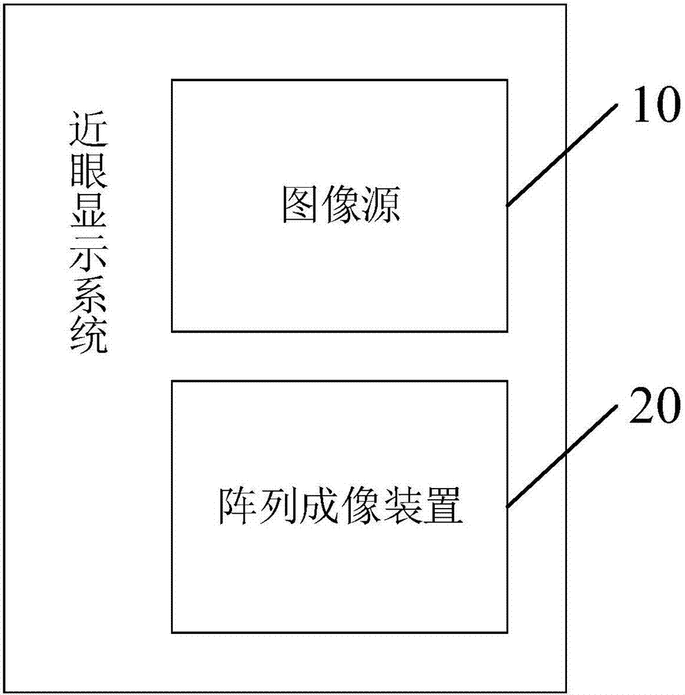
Near-to-eye display system
A near-eye display, human-eye technology, applied in optical components, optics, instruments, etc., can solve problems such as the inability of users to enhance the reality experience, the position limitation of human eye observation, etc., to expand the applicable population, avoid strict restrictions, and avoid adjustment results. imprecise effect
- Summary
- Abstract
- Description
- Claims
- Application Information
AI Technical Summary
Problems solved by technology
Method used
Image

Examples
Embodiment 1
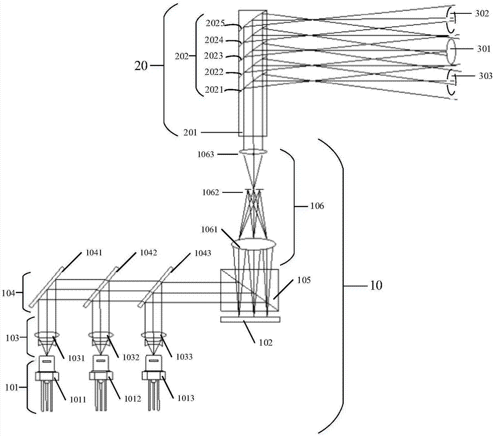
[0041] Please refer to picture 2 , picture 2 Schematic diagram of the first implementation of the near-eye display system provided for Embodiment 1 picture , as shown in the picture 2 As shown, the image source 10 includes:
[0042] an illuminating light source for emitting illuminating light; in this embodiment, the illuminating light source may be a laser generating device 101, as shown in the picture 2As shown, the laser generating device includes a red laser generating unit 1011, a green laser generating unit 1012 and a blue laser generating unit 1013. In another embodiment, the colors of each generating unit in the laser generating device can be set according to actual needs, so as to To meet the needs of the actual situation, there is no limitation here; in other embodiments, the illumination light source can also be an LED light source, and then it can be divided into red light, green light and blue light through a beam splitter, and no limitation is made he...
Embodiment 2
[0058] Please refer to picture 4 , picture 4 Schematic diagram of the second implementation of the near-eye display system provided by the embodiment of the present invention picture , as shown in the picture 4 As shown, image sources 10 include:
[0059] The light source 111 is used to provide initial light; in this embodiment, the light source 111 can specifically be a laser light source, an LED light source, etc., and there is no limitation here;
[0060] The scanning device 112 is arranged on the optical path of the initial light, and is used to deflect the initial light to form an image light; in this embodiment, the scanning device 112 includes a MEMS scanning vibrating mirror 1121, and in this embodiment, the MEMS scanning vibrating mirror It can be composed of a two-dimensional MEMS scanning mirror, or two one-dimensional MEMS scanning mirrors.
[0061]Of course, it should be noted that the initial light is modulated according to the virtual image sent to th...
Embodiment 3
[0066] Please refer to picture 5 , picture 5 Schematic diagram of the third implementation of the near-eye display system provided by the embodiment of the present invention picture , as shown in the picture 5 As shown, image sources 10 include:
[0067] The light source 121 is used to provide initial light; in this embodiment, the light source 121 can specifically be a laser light source, an LED light source, etc., and there is no limitation here;
[0068] The scanning device 122 is arranged on the optical path of the initial light, and is used to deflect the initial light to form an image light; in this embodiment, the scanning device 122 specifically includes an optical fiber scanning device 1221, and the optical fiber scanning device 1221 includes an optical fiber and a scanning drive unit , the scanning driving unit deflects the optical fiber in the horizontal and vertical directions according to the driving signal, and processes the initial light output by the ...
PUM
 Abstract
Description
Claims
Application Information