stone crusher

A stone crusher and main engine technology, applied in stone processing tools, stone processing equipment, work accessories, etc., can solve problems such as unfavorable operation, hydraulic system volume, large weight, limited impact force of stones, etc., and achieve simple structure and portable Convenient and flexible application effects

Active Publication Date: 2019-05-24
清远市金宏基建设有限公司
View PDF5 Cites 0 Cited by
  • Summary
  • Abstract
  • Description
  • Claims
  • Application Information

AI Technical Summary

Problems solved by technology

[0002] In the process of engineering construction, it is often necessary to break rocks or concrete blocks; for this purpose, it is usually necessary to use a breaker; the current breaker mainly includes a hydraulic cannula that can be inserted into a hole prefabricated on the stone, and the hydraulic cannula There is a wedge mechanism on the side of the hydraulic cannula, and the hydraulic cannula is connected to the hydraulic system; when the hydraulic cannula is inserted into the hole, pressurized by the hydraulic system, the wedge mechanism on the side of the hydraulic cannula can be opened horizontally, so that the hole in the stone is horizontal However, since the hydraulic pressure is a static force, it can only increase relatively slowly, and the impact on the stone is very limited. Therefore, the hydraulic system needs to be under a large power to effectively support the stone; another On the one hand, the hydraulic system is bulky and heavy, and it is inconvenient to carry, which is not conducive to working in a flexible and changeable construction environment

Method used


Image

  • stone crusher
  • stone crusher

Examples


Embodiment 1

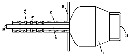
[0013] exist figure 1 In the shown embodiment one, the lithotripter includes a main machine 1; a handrail 11 is provided at the rear of the main machine 1; A shaft 3 that extends axially and extends out of the intubation tube 2; in the first embodiment, the shaft 3 is fixed to the host 1; the outer end of the shaft 3 is provided with a discharge electrode 31 that can generate an arc; The host 1 is provided with a high-voltage power supply, which can apply high voltage to the discharge electrode 31 to make it discharge; two rows of side top mechanisms 4 are evenly distributed on the side of the intubation tube 2 in the circumferential direction, and the side top mechanisms 4 include components that communicate with the inside of the intubation tube. The slideway, and the slide post 41 located in the slideway; the outer end of the slide post 41 forms a pointed cone, and when the slide post 41 laterally slides to the outermost end, the outer end of the slide post 41 is pushed out...

Embodiment 2

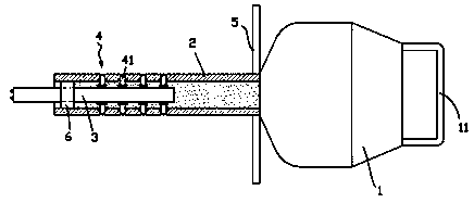
[0018] for figure 2 The second embodiment shown is different from the first embodiment in that the shaft 3 is fixed on the axial sliding plug 6 inside the intubation tube 2; The airtight fit is always maintained, and the airtight fit is always maintained between the sliding column 41 and the slideway; hydraulic oil is sealed in the cannula 2; the sliding column 41 is made of ferromagnet, and in the natural state, each The spool 41 is automatically retracted into the inside of the intubation tube 2 by the attraction of the shaft 3 until the inner end of the swipe 41 touches the shaft 3, and the shaft 3 itself constitutes the inner limit body of each slid 41; The inner end of the sliding column 41 is rounded. In the non-working state, the hydraulic oil in the cannula 2 extends axially to the maximum size, which can make the shaft 3 push out to the limit, and is easy to contact the explosives in the stone hole; When an explosion occurs, the impact force of the high-pressure ga...


PUM


Abstract

The invention provides an efficient stone breaker which comprises a main machine. The main machine forwards extends to form an insertion pipe, a shaft rod which extends along the axis of the insertion pipe and extends out of the insertion pipe is arranged in the insertion pipe, and a discharge electrode capable of generating electric arc is arranged at the outer end of the shaft rod; 2-4 rows of side ejection mechanisms are evenly distributed on the side face of the insertion pipe in the circumferential direction, and each side ejection mechanism comprises a sliding way communicated with the interior of the insertion pipe and a sliding column arranged in the sliding way; and a pointed cone is formed at the outer end of each sliding column, when the sliding columns transversely slide to the outmost ends, the pointed cones at the outer ends of the sliding columns are jacked out of the insertion pipe, and when the sliding columns transversely slide to the innermost ends, the pointed cones at the outer ends of the sliding columns completely contract into the sliding way. By means of the efficient stone breaker, stone blocks or concrete blocks under various environments can be flexible, conveniently and quickly broken, the size and power are small, and carrying is very convenient.

Description

technical field [0001] The invention relates to the field of engineering construction, in particular to a stone crusher. Background technique [0002] In the process of engineering construction, it is often necessary to break rocks or concrete blocks; for this purpose, it is usually necessary to use a breaker; the current breaker mainly includes a hydraulic cannula that can be inserted into a hole prefabricated on the stone, and the hydraulic cannula There is a wedge mechanism on the side of the hydraulic cannula, and the hydraulic cannula is connected to the hydraulic system; when the hydraulic cannula is inserted into the hole, pressurized by the hydraulic system, the wedge mechanism on the side of the hydraulic cannula can be opened horizontally, so that the hole in the stone is horizontal However, because the hydraulic pressure is a static force, it can only increase relatively slowly, and the impact on the stone is very limited. Therefore, the hydraulic system needs to ...

Claims


Application Information

Patent Timeline
Patent Type & Authority Patents(China)
IPC IPC(8): B28D1/14B28D1/00B28D7/00F42D3/04F42D1/18B02C19/18
CPCB02C19/18B28D1/00B28D1/14B28D7/00F42D1/18F42D3/04
Inventor 李聪
Owner 清远市金宏基建设有限公司
Why Eureka
Try Eureka