
Efficient capping machine for filling

A capping machine, high-efficiency technology, applied in the direction of capping the container tightly, packaging, application, etc., can solve the problems of low safety factor, reduce the use efficiency of the device, and the unstable force of the bottle body, so as to reduce the maintenance cost , reduce noise pollution, does not affect the effect of the working environment

Inactive Publication Date: 2017-11-03
王淑兰
View PDF0 Cites 1 Cited by
  • Summary
  • Abstract
  • Description
  • Claims
  • Application Information

AI Technical Summary

Problems solved by technology

[0002] At present, in the food or pharmaceutical industry, such as wine bottles, canned food, bottled medicines, etc., for the convenience of storage and transportation, we generally seal the processed products with caps. Most of the current sealing methods use manual pressing or The operation method of knocking the bottle cap with a rubber rod is not only slow, but also labor-intensive. Long-term high-intensity labor causes the physical strength of the worker to decline, which makes the pressing force insufficient and the bottle cap is not pressed tightly. A lot of defective products are caused. In order to solve the above problems, there are corresponding capping devices on the market, but these devices lack the structure for fixing the bottle body, and the problem of unstable force on the bottle body is prone to occur.
In addition, because the distance between the capping track and the conveying track of the existing continuous capping machine is fixed, when encountering bottles of different heights, the continuous capping machine will not work normally, which may cause the bottle cap to not be touched Or the situation that the bottle full of camellia oil is knocked over occurs, the universality is poor, the safety factor is low, and it will seriously affect the work efficiency, causing the indirect increase of the production cost, and generally a shock-absorbing spring is added at the lower end of the device to reduce the Shock, when the shock absorbing spring has been used for a long time, the elastic fatigue life of the shock absorbing spring is reduced, which affects the elastic force. At this time, it is necessary to replace the shock absorbing spring to achieve adjustment. Frequent replacement of the shock absorbing spring greatly increases the maintenance cost and reduces device efficiency

Method used

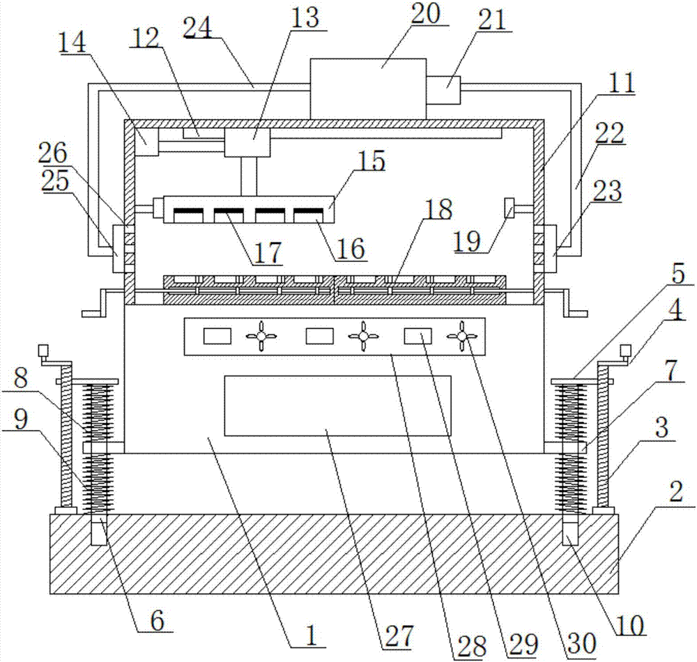
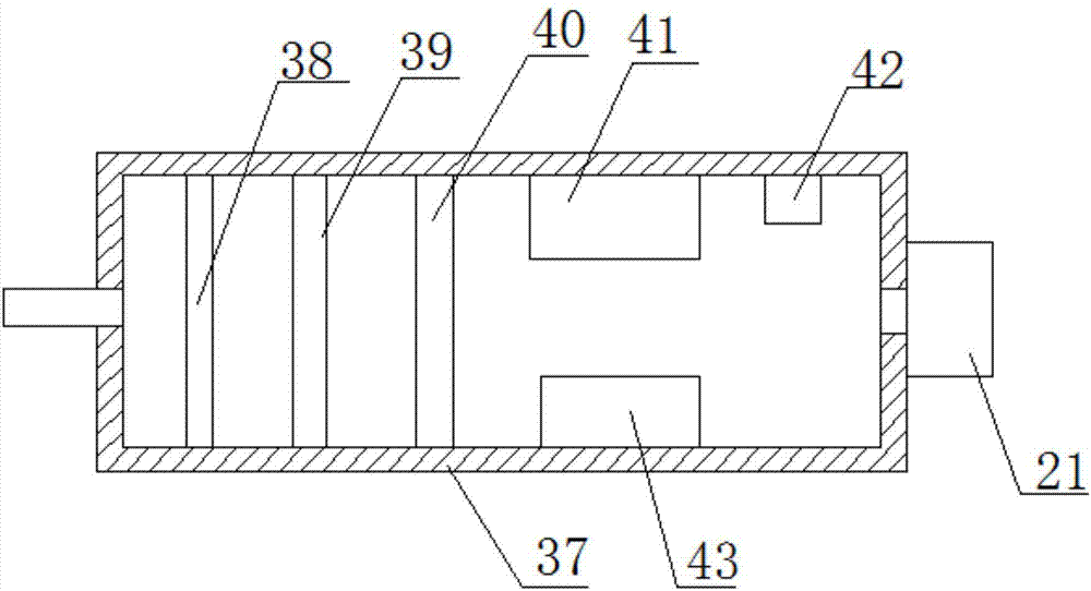
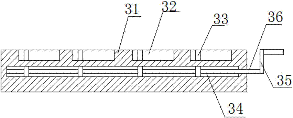

Image

  • Efficient capping machine for filling
  • Efficient capping machine for filling
  • Efficient capping machine for filling

Examples


Embodiment Construction

[0016] The following will clearly and completely describe the technical solutions in the embodiments of the present invention with reference to the accompanying drawings in the embodiments of the present invention. Obviously, the described embodiments are only some, not all, embodiments of the present invention. Based on the embodiments of the present invention, all other embodiments obtained by persons of ordinary skill in the art without making creative efforts belong to the protection scope of the present invention.

[0017] see Figure 1~3 , in an embodiment of the present invention, a high-efficiency capping machine for filling, including a workbench 1 and a base 2, an anti-skid pad is provided on the lower side of the base 2, and the left and right ends of the upper side of the base 2 pass through the connecting seat A first threaded rod 3 is installed, the upper end of the first threaded rod 3 is connected with a first rotating handle 4, the first threaded rod 3 is thre...


PUM


Abstract

The invention discloses a high-efficiency capping machine for filling, which comprises a workbench and a base. A machine cover is arranged on the upper side of the workbench, and a guide rail is arranged on the inner top of the machine cover. There is a second hydraulic cylinder on the upper left side of the interior, and the right end of the second hydraulic cylinder is connected to the left side of the first hydraulic cylinder. The left side of the hood is provided with a suction hood, the upper end of the hood is provided with a purification box, the purification box is connected to the suction hood through a suction pipe, the right end of the purification box is provided with a fan, and the outlet of the fan is provided with an outlet Air duct, the other end of the air outlet duct is provided with an air outlet cover, the air outlet cover is arranged on the right side of the hood and communicates with the inside of the hood through several through holes. The invention has the advantages of simple structure, convenient use, high capping efficiency, good capping effect, high use comfort and long service life, and can prevent products from being polluted.

Description

technical field [0001] The invention relates to the technical field of capping devices, in particular to a high-efficiency capping machine for filling. Background technique [0002] At present, in the food or pharmaceutical industry, such as wine bottles, canned food, bottled medicines, etc., for the convenience of storage and transportation, we generally seal the processed products with caps. Most of the current sealing methods use pure manual pressing or The operation method of knocking the bottle cap with a rubber rod is not only slow, but also labor-intensive. Long-term high-intensity labor causes the physical strength of the worker to decline, which makes the pressing force insufficient and the bottle cap is not pressed tightly. Cause a lot of defective products, in order to solve the above-mentioned problem also has corresponding capping device on the market, but all lacks the structure that is used for fixing the bottle body in this device, easily occurs the problem t...

Claims


Application Information

Patent Timeline
IPC IPC(8): B67B3/00
CPCB67B3/00
Inventor 王淑兰
Owner 王淑兰
Learn More