Permanent magnet coupling buffer protector

A technology of permanent magnet coupling and protector, used in permanent magnet clutches/brakes, clutches, automatic clutches, etc., can solve the problems of ineffective protection of high-speed gearboxes, difficulty in installation, maintenance, and thinning of friction lining loss. , to achieve the effect of reducing maintenance costs, eliminating torsional vibration, eliminating impact load and vibration

Pending Publication Date: 2019-08-16
JIANGSU MAGNET VALLEY TECH
View PDF2 Cites 2 Cited by
  • Summary
  • Abstract
  • Description
  • Claims
  • Application Information

AI Technical Summary

Problems solved by technology

However, this torque limiter has many defects: First, in order to protect the reliability of the coupling, the slipping torque value of the coupling will be set larger to prevent it from slipping frequently, because once it slips, it must be manually Re-tighten with a wrench to form a pre-tightening force again, and it cannot be reset automatically; but if the slipping torque is set too large, it cannot effectively protect the high-speed gearbox
Second, the friction plate will be worn out and thinned after frequent slipping, and the installation of the entire coupling needs to be adjusted, making construction difficult
[0005] The above-mentioned particularity of the wind turbine unit makes its installation, repair, and maintenance very difficult. In order to ensure the power generation, the equipment must have high reliability and maintenance-free characteristics.

Method used


Image

  • Permanent magnet coupling buffer protector
  • Permanent magnet coupling buffer protector
  • Permanent magnet coupling buffer protector

Examples


Embodiment 1

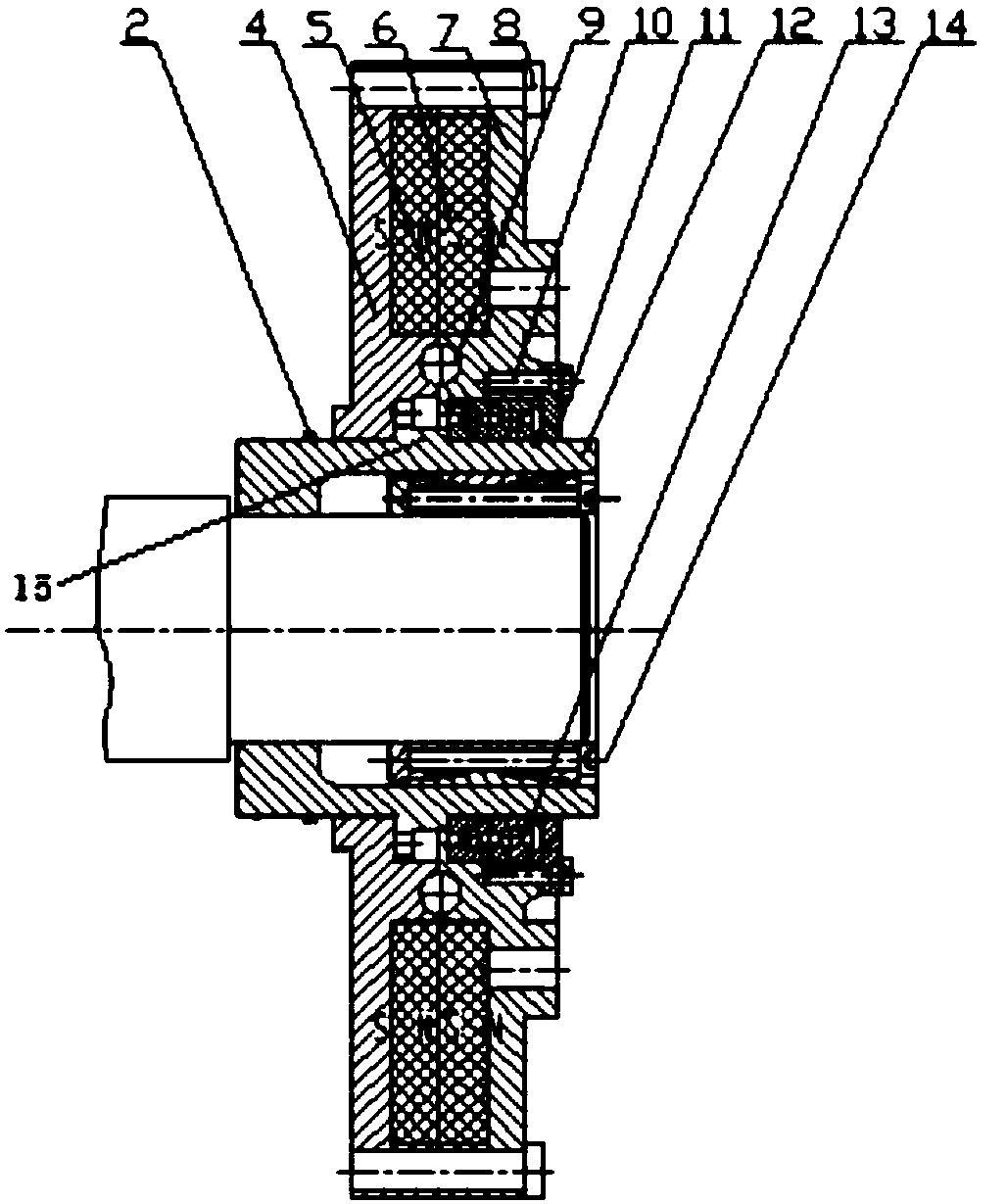
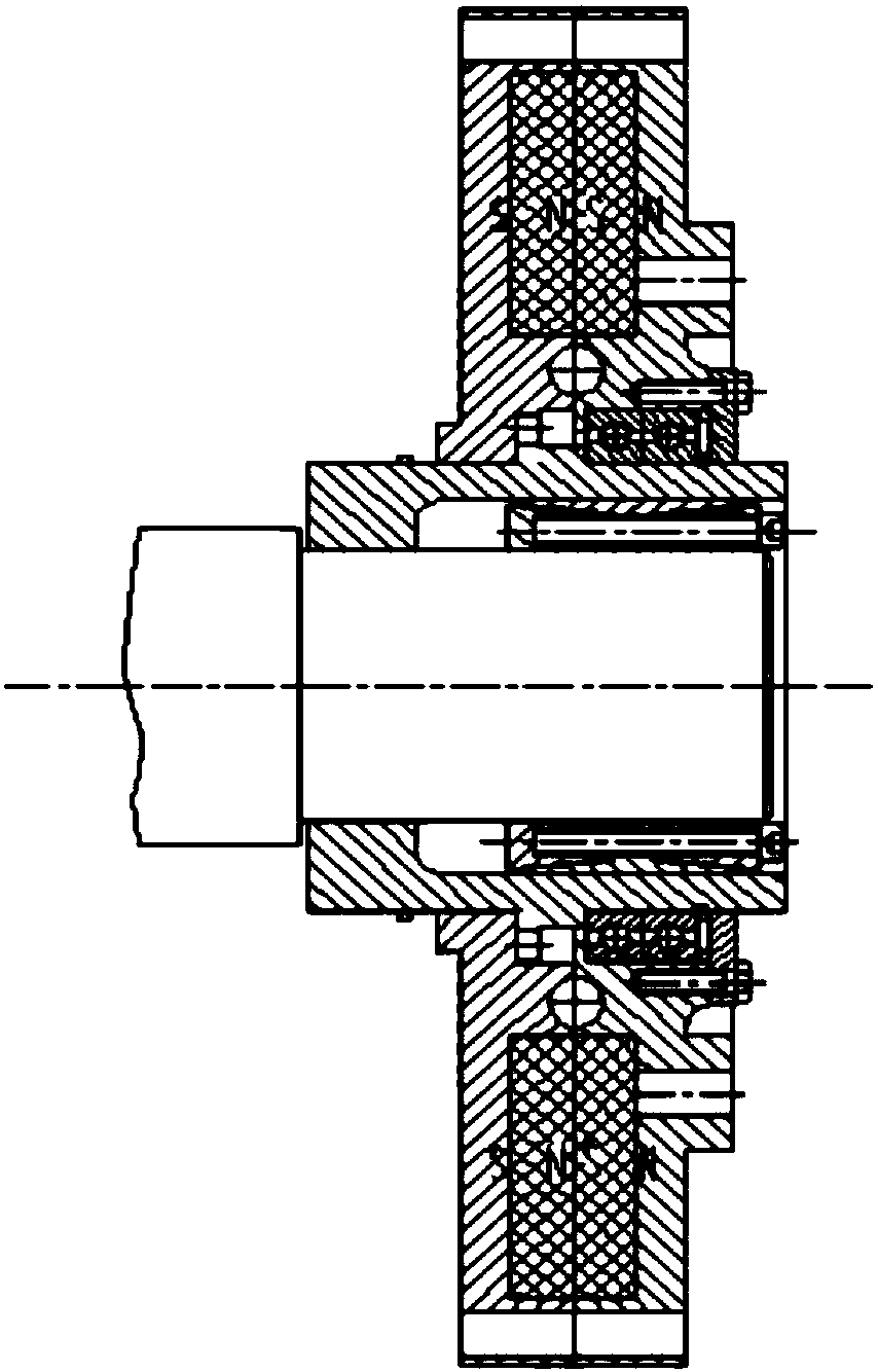
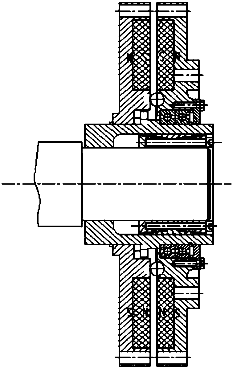
[0055] Such as Figure 1-5 Shown is a wind power permanent magnetic coupling buffer protector according to the first preferred embodiment of the present disclosure.

[0056] figure 1 It is a structural schematic diagram of the present disclosure. The wind power permanent magnet coupling buffer protector includes a limit stop ring 2, a driven plate 4, a driven permanent magnet 5, an active permanent magnet 6, an active plate 7, a linkage pin 8, and a marble 9 , Connecting bolts 10, bearing end cap 11, bushing 12, bearing 13, expansion sleeve 14, middle raised part 15.

[0057] The driving disk 7 is connected to the driving end (such as the output shaft of the speed-increasing gearbox), and the active permanent magnet 6 is fixedly installed on the driving disk. The magnetization direction of the permanent magnet is perpendicular to the axial direction, and the fixed installation form of the permanent magnet is N, S Staggered. A driven permanent magnet 5 is installed on the co...

Embodiment 2

[0072] The specific implementation manner of the present disclosure can also be the second preferred wind power permanent magnetic coupling buffer protector. The difference between it and the previous embodiment is that the meshing between the driven disc 4 and the bushing 12 of this embodiment adopts the face tooth meshing method, and bevel gears are respectively arranged on the contacting end faces of the driven disc 4 and the bushing 12, such as Figure 6 As shown, it is the structural form of bevel gear shaft intersection angle Σ=180°, and the number of teeth is n times the number of driven permanent magnets.


PUM


Abstract

The invention discloses a permanent magnet coupling buffer protector. The permanent magnet coupling buffer protector comprises a driving disc, a driven disc and a shaft sleeve with an limiting bafflering and an intermediate protruding part on the outer surface, wherein the shaft sleeve is fixed to a driven shaft through a power lock, and the driving disc is supported on the shaft sleeve through abearing; the driven disc and the shaft sleeve are slidably connected and transmit torque, and the shaft sleeve separately limits slidable positions, away from and close to the driving disc, of the driven disc through the limiting baffle ring and the intermediate protruding part; an inner recess part accommodating a part of a rolling body is formed in the end surface of the driving disc, and the driven disc is provided with a slide for enabling the rolling body to roll. The permanent magnet coupling buffer protector slips without vibration during coupling transmission of torque, provides an infinite buffer angle, automatically resets after slipping, completely eliminates the torsional vibration generated by variable loads, eliminates impact loads and vibration of a high-speed gear box of awind generation set, reduces the maintenance and repair cost of the gear box, prolongs the service life of a complete set of transmission system equipment, and improves the safety factor of an entiresystem.

Description

technical field [0001] The present disclosure relates to the field of permanent magnet overload buffer protection, in particular, to a high-speed dynamic load buffer protection device for transmission of a wind power generating set. Background technique [0002] Faced with the current situation of increasing global energy shortage, people began to pay more attention to the research and development of new energy sources, such as the development of wind energy and solar energy, which can effectively alleviate my country's energy supply dilemma. Among them, wind energy is the most mature industrialization condition, such as using wind energy to generate electricity. However, the development of wind power also faces many difficulties. For example, wind power generation equipment needs to meet the requirements of reliable operation for 20-30 years under field conditions, and it should also be able to withstand the test of various extreme weather and very heavy alternating wind loa...

Claims


Application Information

Patent Timeline
Patent Type & Authority Applications(China)
IPC IPC(8): F16D7/00F16D43/00H02K49/10
CPCF16D7/00F16D43/00H02K49/108Y02E10/72
Inventor 徐俊峰杨可银
Owner JIANGSU MAGNET VALLEY TECH
Why Eureka
Try Eureka