A friction rod transmission device

A transmission device, friction rod technology, applied in the direction of measuring devices, instruments, etc., can solve the problems of difficult to eliminate the return gap, peeling off of the polished rod, incapable of high load, etc., to improve the transmission efficiency and stability, reduce fatigue damage, and increase service life. Effect

Active Publication Date: 2019-09-27
深圳力合精密装备科技有限公司
View PDF6 Cites 0 Cited by
  • Summary
  • Abstract
  • Description
  • Claims
  • Application Information

AI Technical Summary

Problems solved by technology

Various transmission methods have their own advantages; the rack and pinion transmission has a large load and can be extended infinitely, but the return gap is difficult to eliminate and the cost is high; the reciprocating motion of the ball screw transmission has no gap, and the repeat positioning accuracy is high, but the direction of gravity, the screw itself The deformation is large, and the stroke should not be too long; the price of the belt drive is cheap, but the stroke should not be too long, and the energy conversion efficiency is low; the return stroke of the friction rod drive has no gap, the noise is low, but the load should not be too high
The invention relates to a friction rod transmission device, which is used for two axes in a three-coordinate measuring machine with a low load, so as to overcome the defect that the friction rod transmission itself cannot carry a high load
[0005] The friction rod transmission is a clamping part and the polished rod extruding each other to generate static friction, which provides power to the moving parts. The quality of the clamping part directly determines the entire transmission efficiency and stability of the friction rod transmission. Improper installation of the polished rod itself will make When the clamping part and the polished rod are squeezed, due to the uneven force, the polished rod will peel off prematurely, twist and other fatigue failures, which will reduce the service life of the friction rod transmission

Method used


Image

  • A friction rod transmission device
  • A friction rod transmission device
  • A friction rod transmission device

Examples


Embodiment

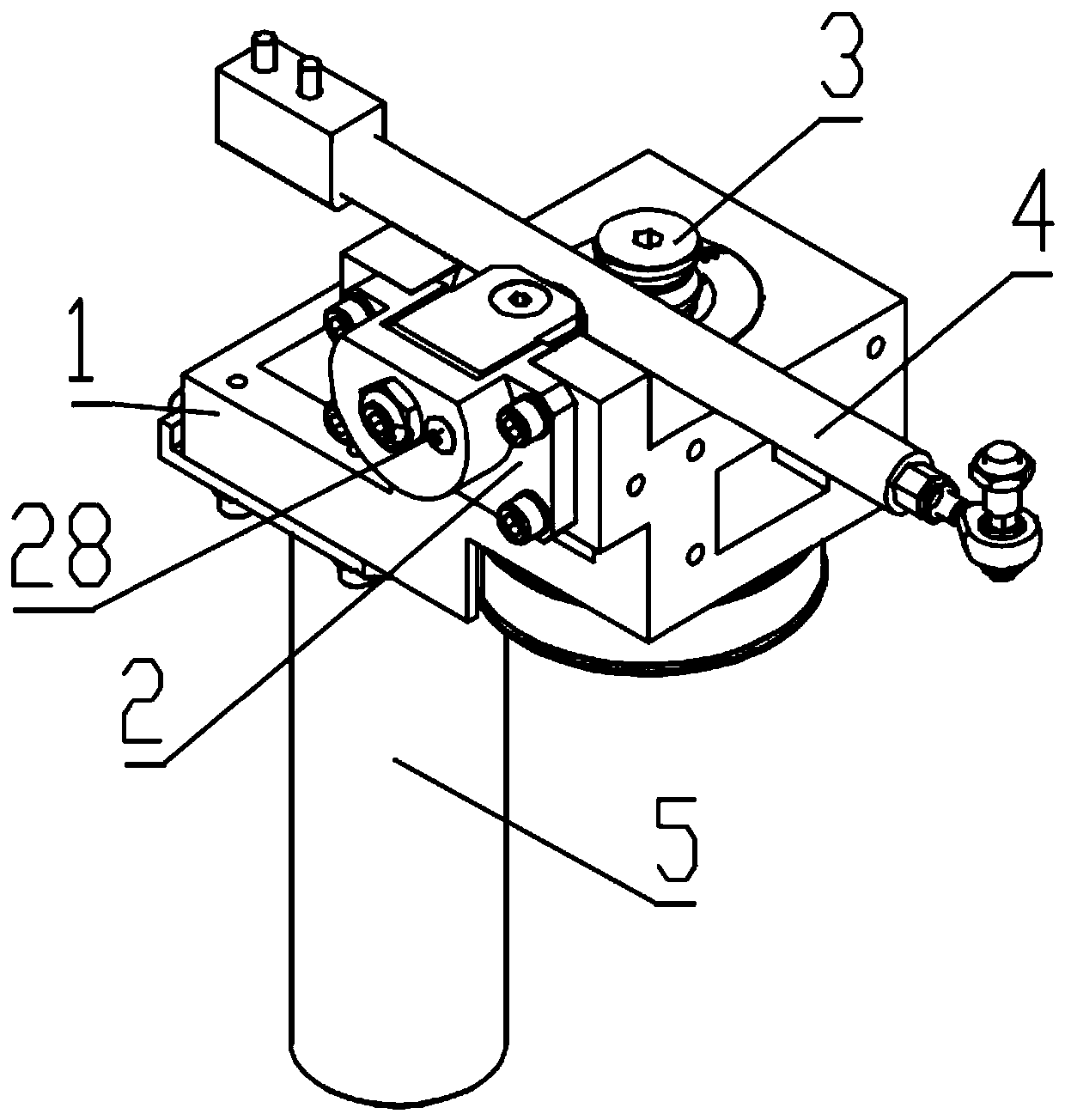
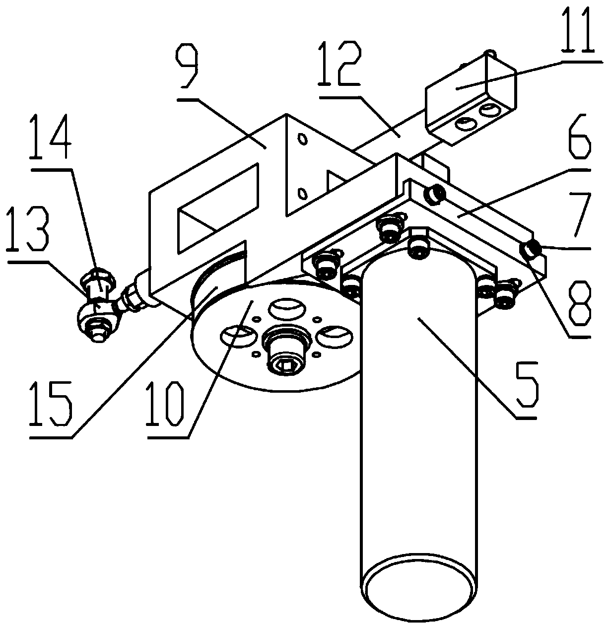
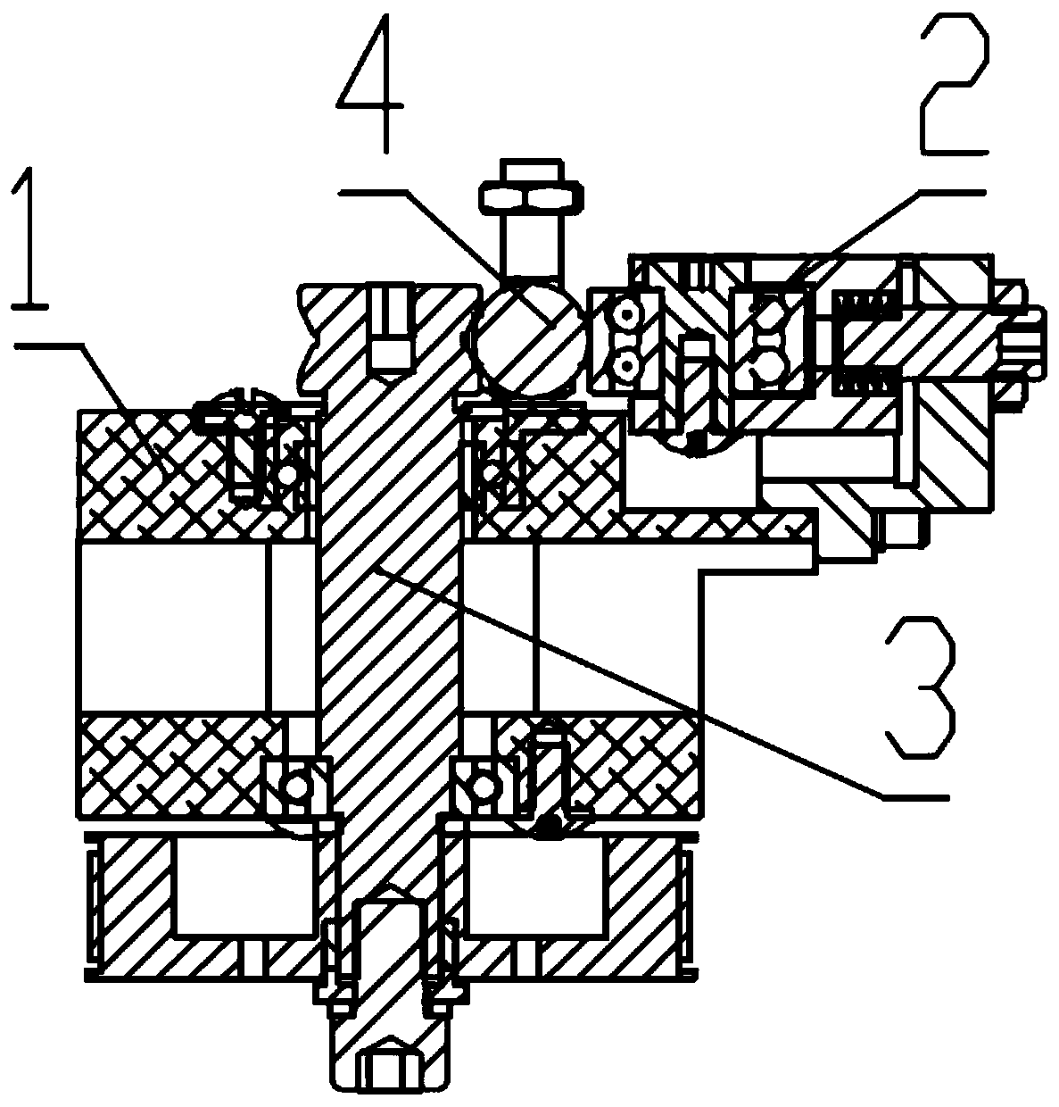
[0034] like Figure 1 to Figure 3 As shown, a friction rod transmission device shown in this embodiment includes a box body 9 and a V-shaped wheel assembly 3 installed on the box body 9, a friction rod assembly 4, a pressing wheel assembly 2 and a servo motor 5, the servo The motor 5 is set at the lower end of the box body 9 and is connected to the V-shaped wheel assembly 3. The pressing wheel assembly 2 is set at the upper end of the box body 9 and clamps the friction rod assembly 4 with the V-shaped wheel assembly 3. The V-shaped wheel assembly is driven by the servo motor 5. The wheel assembly 3 rotates, and the V-shaped wheel assembly 3 then generates static friction with the friction rod assembly 4. The static friction generates a forward thrust on the friction rod assembly 4, pushing the friction rod assembly 4 forward. When the friction rod assembly 4 moves to the specified position, an active force in the opposite direction is generated to force the friction rod assemb...


PUM


Abstract

The invention discloses a friction rod transmission device. The device comprises a box body as well as a V-shaped wheel assembly, a friction rod assembly, a pressing wheel assembly and a servo motor which are all arranged on the box body; the servo motor is arranged at the lower end of the box body and is in transmission connection with the V-shaped wheel assembly; and the pressing wheel assembly is arranged at the upper end of the box body and clamps the friction rod assembly with the V-shaped wheel assembly. The servo motor drives the V-shaped wheel assembly to rotate, so that the V-shaped wheel assembly in turn generates a static friction force with the friction rod assembly; the static friction force generates a forward pushing force to the friction rod assembly, so that the friction rod assembly can be pushed to move forward; when the friction rod assembly moves to a specific position, an acting force of an opposite direction is generated so as to force the friction rod assembly to stop moving; and therefore, a whole movement process can be completed. According to the friction rod transmission device of the invention, the efficiency and stability of the entire transmission of the friction rod can be increased, and the service life of the friction rod can be prolonged.

Description

technical field [0001] The invention relates to a friction rod transmission device used in transmission occasions with low load and high requirements for repeated positioning accuracy in precision instruments such as a three-coordinate measuring machine or a two-dimensional geometric measuring instrument. Background technique [0002] The main frame of the three-coordinate measuring machine is composed of three axes. Under the action of the controller, each axis moves in its own direction. During the transmission process, due to the inertia of the machine tool itself and the error in the machining accuracy of the parts, the three-coordinate measuring machine moves in three directions. There are twenty-one errors on the surface: the position degree in three directions; the six straightness degrees when moving in three directions; the nine angular pendulums in autobiography, pitch and direction when moving in three directions; Spend. The twenty-one errors can be attributed to...

Claims


Application Information

Patent Timeline
Patent Type & Authority Patents(China)
IPC IPC(8): G01B21/00
Inventor 陶彦博
Owner 深圳力合精密装备科技有限公司
Why Eureka
Try Eureka