Cloth chute device for cloth machine

A technology for distributing chute and distributing machine, applied in the direction of supply device, manufacturing tools, etc., which can solve the problems of high manufacturing cost, many failures, complicated lifting of the upper and lower mechanism of the distributing machine outlet, etc., and achieves low manufacturing cost, low failure rate and simple structure Effect

Inactive Publication Date: 2017-11-07
河北华远冶金设备有限公司
View PDF5 Cites 4 Cited by
  • Summary
  • Abstract
  • Description
  • Claims
  • Application Information

AI Technical Summary

Problems solved by technology

[0003] The technical problem solved by the present invention is to provide a material distribution chute device for a material distribution machine, which solves the problems in the prior art that the upper and lower mechanisms of the material distribution machine outlet are complicated to lift, high manufacturing cost, and many failures.

Method used


Image

  • Cloth chute device for cloth machine
  • Cloth chute device for cloth machine
  • Cloth chute device for cloth machine

Examples


Embodiment 1

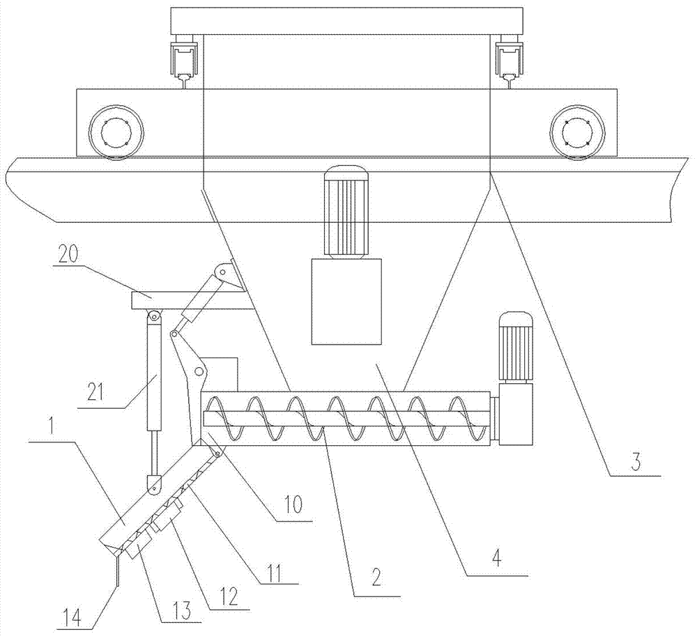
[0031] Example one: such as figure 1 As shown, at the bottom of the cloth hopper 4 of the cloth machine 3, there is a twisting cage feeding device 2, and the left side of the twisting cage feeding device 2 is a cloth outlet 10. The present invention includes a cloth chute 1 hinged to the bottom of the cloth outlet 10 and one end installed at The other end of the cloth machine 3 is connected with the cloth chute 1 and is used to drive the cloth chute 1 to swing along the hinge point.

[0032] The shape of the distributing chute 1 can be a cylinder, a rectangular tube, a cone-shaped tube, a semi-circular groove, a U-shaped groove and a flat plate.

[0033] The inner side wall of the distributing chute 1 is provided with a polymer polymer plate 11, and the polymer polymer plate 11 can effectively reduce the friction force from the inner side wall of the distributing chute 1 on the material during the discharging process.

[0034] A vibrating motor 12 is arranged on the outer side wall o...

Embodiment 2

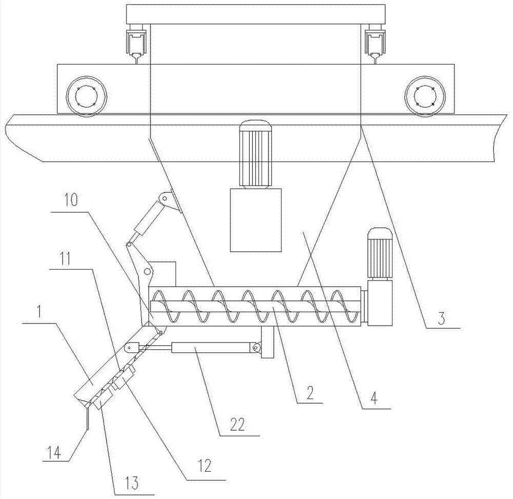
[0038] Embodiment two: such as figure 2 As shown, on the basis of Embodiment 1, the structure of the driving device is changed without the other structure. The driving device includes a pusher whose one end is hinged with the bottom of the cloth machine 3 and the other end is hinged with the surface or side of the cloth chute 1. The second rod 22; the second push rod 22 can be a hydraulic push rod or an electric push rod. The push rod 22 pushes its piston to move axially and drives the cloth chute 1 to swing around its hinge point with the outlet 10 of the cloth machine, and then the outlet end of the cloth chute 1 is displaced up and down, that is, the cloth The height of the outlet end of the chute 1 changes, and the operation can be adjusted according to the actual situation to realize the production of concrete parts of different thicknesses.

Embodiment 3

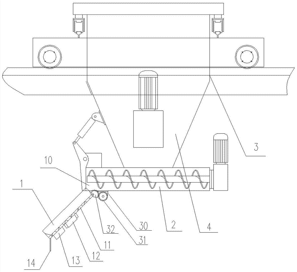
[0039] Example three: such as image 3 As shown, on the basis of Embodiment 1, the structure of the driving device is changed without the other structure. The driving device includes a motor 30 installed at the bottom of the cloth machine 3 and a drive shaft installed on the motor 30. The number gear 31 and the number two gear 32 meshed with the number one gear 31; the number two gear 32 is arranged on the distribution chute 1 and the distribution chute 1 can rotate with the number two gear 32. The motor drives the second gear 32 to rotate through the rotation of the first gear 31, and then the second gear 32 drives the cloth chute 1 hinged to the cloth outlet 10 of the cloth machine to swing, so that the outlet end of the cloth chute 1 Up and down displacement occurs, that is, the height of the outlet end of the distributing chute 1 changes, and adjustment operations can be performed according to actual conditions to realize the production of concrete parts of different thickne...


PUM


Abstract

The invention relates to a cloth chute device for a cloth machine. The cloth chute device comprises a cloth chute and a driving device, wherein the cloth chute is hinged to the bottom of a cloth outlet of the cloth machine; and one end of the driving device is mounted onto the cloth machine, and the other end of the driving device is connected with the cloth chute. The cloth chute serves as a cloth machine accessory which is arranged externally, can be rapidly and conveniently mounted at a discharging opening of the cloth machine and is convenient to demount. By means of the cloth machine, the height of an outlet of the cloth chute is adjusted through the driving device; the cloth chute can be better adapted to production of concrete parts of different thicknesses; the cloth chute is simple in structure, low in failure rate and low in production cost; when the cloth chute is in the feeding process, compared with the mode that a whole feeding funnel moves up and down, vertical displacement of a discharging opening of the cloth chute is achieved through swing of the cloth chute under the effect of small driving force, and height adjustment can also be achieved; the requirement that the cloth chute device is adapted to different workpieces is met; the structure is simple; and the driving device operates independently and is not prone to failure, so that reliability is high.

Description

Technical field [0001] The invention relates to a distributing equipment, in particular to a distributing chute device for a distributing machine. Background technique [0002] As an indispensable construction engineering equipment, it is widely used in the construction of cement, concrete and other materials during construction. The general distributing machine is usually composed of a main body bracket, a longitudinal cart and a horizontal cart traveling mechanism, and a distributing bucket. The longitudinal and lateral movement of the cloth bucket is realized by the walking of the longitudinal cart and the horizontal cart on the support rail. However, it is difficult for the ordinary distributor to realize the vertical movement of the distributor bucket and cannot realize the production of concrete parts of different thicknesses. CN102995902A discloses a spiral cloth machine, the upper frame of the cloth hopper and the cloth hopper are connected by a plurality of oil cylinde...

Claims


Application Information

Patent Timeline
Patent Type & Authority Applications(China)
IPC IPC(8): B28B13/02
CPCB28B13/02B28B13/0215
Inventor 李玉清
Owner 河北华远冶金设备有限公司
Why Eureka
Try Eureka