
High-efficiency air compressor heat recovery system

A high-efficiency air and compressor technology, used in mechanical equipment, machines/engines, liquid fuel engines, etc., can solve the problems of accelerated greenhouse effect, less heat in water, and poor taste of hot water.

Active Publication Date: 2017-11-07
上海赛捷能源科技有限公司
View PDF6 Cites 2 Cited by
  • Summary
  • Abstract
  • Description
  • Claims
  • Application Information

AI Technical Summary

Problems solved by technology

[0002] The air compressor will generate a lot of compression heat during operation. At present, an external cooling system is used for cooling, and the heat is directly discharged into the atmosphere through the cooling tower. This is not only a waste of energy, but also accelerates the greenhouse effect. Some users also The heat of compression has been initially used, and the heat in the cooling water of the centrifugal compressor is only recycled. This part of the water has less heat and the taste of hot water is not high.

Method used


Image

  • High-efficiency air compressor heat recovery system

Examples


Embodiment Construction

[0032] Embodiments of the present invention are described in detail below, examples of which are shown in the drawings, wherein the same or similar reference numerals designate the same or similar elements or elements having the same or similar functions throughout. The embodiments described below by referring to the figures are exemplary and are intended to explain the present invention and should not be construed as limiting the present invention.

[0033] The heat recovery system for a high-efficiency air compressor according to an embodiment of the present invention will be described in detail below with reference to the accompanying drawings.

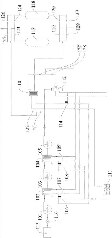
[0034] A high-efficiency air compressor heat recovery system according to an embodiment of the present invention includes: a first compressor 101, a first heat exchanger 102, a second compressor 103, a second heat exchanger 104, and a third compressor 105, The third heat exchanger 106, the first three-way valve 107, the fourth heat...


PUM


Abstract

The embodiment of the invention discloses a high-efficiency air compressor heat recovery system. The system comprises a first compressor, a first heat exchanger, a second compressor, a second heat exchanger, a third compressor, a third heat exchanger, a first three-way valve, a fourth heat exchanger, a second three-way valve, a fifth heat exchanger, a heat preserving water tank, a first drying tower, a second drying tower, a first valve, a second valve, a third valve, a fourth valve, a fifth valve, a sixth valve, a first connecting branch, a seventh valve and an eighth valve. By means of the high-efficiency air compressor heat recovery system disclosed by the embodiment of the invention, the heat recovery can be effectively carried out.

Description

technical field [0001] The invention relates to the field of air compressor energy saving, in particular to a high-efficiency air compressor heat recovery system. Background technique [0002] The air compressor will generate a lot of compression heat during operation. At present, an external cooling system is used for cooling, and the heat is directly discharged into the atmosphere through the cooling tower. This is not only a waste of energy, but also accelerates the greenhouse effect. Some users also The heat of compression has been initially used, but the heat in the cooling water of the centrifugal compressor is recycled. This part of the water has less heat and the taste of hot water is not high. Contents of the invention [0003] The present invention aims to solve one of the technical problems in the related art at least to a certain extent. [0004] Therefore, an object of the present invention is to propose a high-efficiency air compressor heat recovery system t...

Claims


Application Information

Patent Timeline
Patent Type & Authority Applications(China)
IPC IPC(8): F04D29/58
CPCF04D29/5826
Inventor 陆小科阎峰
Owner 上海赛捷能源科技有限公司
Learn More