Heat energy recovery system for sludge drying tail gas of paddle dryer and use method of heat energy recovery system

A heat recovery and sludge drying technology, which is applied in dehydration/drying/thickening sludge treatment, drying, heat exchange equipment, etc., can solve the problems of inability to use waste heat of sludge drying tail gas, heat loss, etc.

Active Publication Date: 2021-10-01
ZHEJIANG UNIV
View PDF7 Cites 2 Cited by
  • Summary
  • Abstract
  • Description
  • Claims
  • Application Information

AI Technical Summary

Problems solved by technology

[0006] The technical problem to be solved by the present invention is to overcome the difficulty that the waste heat of sludge drying tail gas cannot be used in the existing sludge drying-incineration disposal technical scheme. At present, the sludge drying tail gas of the paddle dryer usually uses a condenser Condensate and separate the condensate in the tail gas, resulting in a large loss of heat energy

Method used


Image

  • Heat energy recovery system for sludge drying tail gas of paddle dryer and use method of heat energy recovery system
  • Heat energy recovery system for sludge drying tail gas of paddle dryer and use method of heat energy recovery system

Examples


Embodiment Construction

[0025] The present invention will be further described below in combination with the specific embodiments in the accompanying drawings.

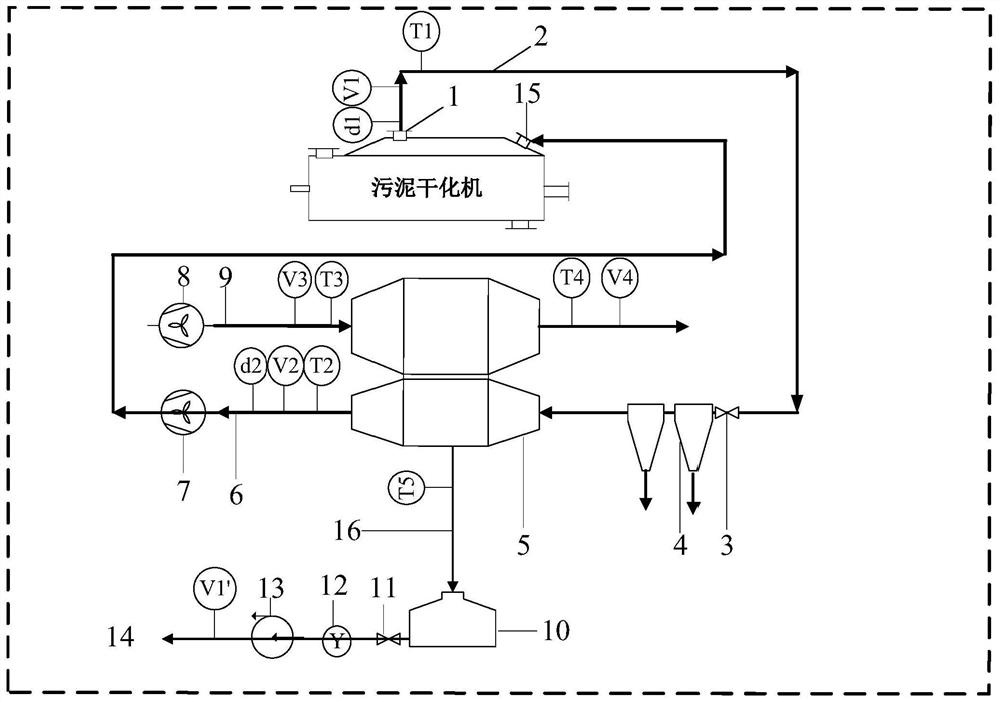
[0026] refer to figure 1 , a schematic diagram of a heat recovery system for sludge drying tail gas of a paddle dryer, including a gas delivery pipe 2 connecting the tail gas outlet 1 of the dryer and the inlet of the evaporation section of the heat pipe 5, and also including an air valve 3 and a cyclone dust collector 4. The gas pipeline is connected to the gas valve 3, the cyclone dust collector 4 and the inlet of the heat pipe 5 respectively in sequence; the first gas hygrometer d1, flow meter V1 and temperature Sensor T1 is used to monitor the moisture content, flow rate and temperature of the exhaust gas in real time; in order to reduce the heat loss of the exhaust gas, this section of the pipeline is covered with thermal insulation cotton. At the outlet of the evaporation section of the heat pipe 5, the pipe 6 is connected to the indu...


PUM


Abstract

The invention relates to a heat energy recovery system for sludge drying tail gas of a sludge drying incineration plant, in particular to a heat energy recovery system for the sludge drying tail gas of a paddle dryer, which is used for recovering heat of tail gas generated in the drying process of sludge in the paddle dryer by utilizing a two-phase closed thermosiphon and a use method of the heat energy recovery system. When the system runs, the sludge is dried, gas enters the evaporation section of a heat pipe under the action of an induced draft fan, through heat exchange with a working medium in the heat pipe, a large amount of heat released by the tail gas is transferred to the working medium in the heat pipe due to the efficient heat transfer performance of the heat pipe, so that the working medium in the heat pipe is subjected to phase change and ascends to be transferred to the condensation section of the heat pipe and exchange heat with fresh air entering the heat pipe through the induced draft fan; and after heat is transferred to the fresh air, the working medium is liquefied and enters the evaporation section again under the action of gravity, and the working medium circulates in the heat pipe to complete waste heat utilization of the sludge drying tail gas.

Description

technical field [0001] The invention relates to a heat energy recovery system for sludge drying tail gas in a sludge drying incineration plant. Specifically, a two-phase closed thermosiphon is used to treat the tail gas generated during the drying process of the sludge in a paddle type dryer. A heat energy recovery system for paddle dryer sludge drying tail gas for heat recovery and a use method thereof. Background technique [0002] Heat pipe is a high-efficiency heat transfer technology developed in the early 1960s, which was first used in space technology and aerospace military fields. Because the heat pipe has the advantages of high heat transfer efficiency, simple structure, stable performance, and low cost, it is widely used in chemical, petrochemical, power, metallurgy, glass and other industries. There are many ways to classify heat pipes. According to the return flow force of the working liquid, they can be divided into core heat pipes, two-phase closed thermosipho...

Claims


Application Information

Patent Timeline
Patent Type & Authority Applications(China)
IPC IPC(8): F28D15/02F28F27/02F26B25/00C02F11/13
CPCF28D15/02F28F27/02F26B25/005C02F11/13Y02P70/10
Inventor 王飞吕卢凯
Owner ZHEJIANG UNIV
Why Eureka
Try Eureka